Facebook
 Google
 GitHub
 Linkedin
Digital Circuits
Microcontroller Principles
20 questions By Tony R. Kuphaldt
-
Question 16 of 20
Examine the following schematic diagram and program listing (written in “pseudocode” rather than a formal programming language) to determine what type of basic logic function is being implemented in this microcontroller unit:
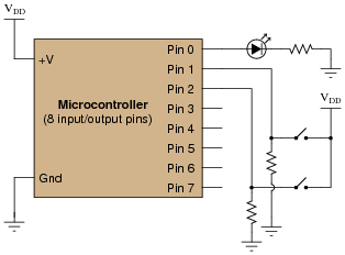
Pseudocode listing Declare Pin0 as an output
Declare Pin1 and Pin2 as inputs
LOOP
IF Pin1 is same as Pin2, set Pin0 HIGH
ELSE set Pin0 LOW
ENDIF
ENDLOOP
Reveal answerThis microcontroller implements the logical Exclusive-NOR function.
Notes:Although this logic function could have been implemented easier and cheaper in hard-wired (gate) logic, the purpose is to get students to think of performing logical operations by a sequenced set of instructions inside a programmable device (the MCU). This is a conceptual leap, basic but very important.
In case you’re wondering why I write in pseudocode, here are a few reasons:
- No prior experience with programming required to understand pseudocode
- It never goes out of style
- Hardware independent
- No syntax errors
If I had decided to showcase code that would actually run in a microcontroller, I would be dooming the question to obsolescence. This way, I can communicate the spirit of the program without being chained to an actual programming standard. The only drawback is that students will have to translate my pseudocode to real code that will actually run on their particular MCU hardware, but that is a problem guaranteed for some regardless of which real programming language I would choose.
Of course, I could have taken the Donald Knuth approach and invented my own (imaginary) hardware and instruction set . . .
-
Question 17 of 20
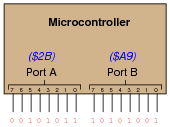
Digital computers communicate with external devices through ports: sets of terminals usually arranged in groups of 4, 8, 16, or more. These terminals may be set to high or low logic states by writing a program for the computer that sends a numerical value to the port. For example, here is an illustration of a microcontroller being instructed to send the hexadecimal number 2B to port A and A9 to port B:
Suppose we wished to use the first seven bits of each port (pins 0 through 6) to drive two 7-segment, common-cathode displays, rather than use BCD-to-7-segment decoder ICs:
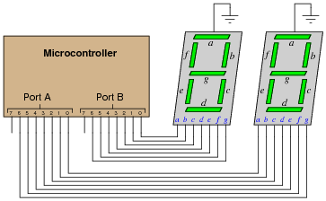
Write the necessary hexadecimal values to be output at ports A and B to generate the display “42” at the two 7-segment display units.
Reveal answerPort A = 5B16 Port B = 6616
Note that the following answers are also valid:
Port A = DB16 Port B = E616
Follow-up question: write these same numerical values in decimal rather than hexadecimal.
Notes:The root of this question is little more than binary-to-hexadecimal conversion, but it also introduces students to the concept of controlling bit states in microcomputer ports by writing hex values. As such, this question is very practical! Although it is unlikely that someone would omit BCD-to-7-segment decoders when building a two-digit decimal display (because doing it this way uses so many more precious microcontroller I/O pins), it is certainly possible! There are many applications other than this where you need to get the microcontroller to output a certain combination of high and low states, and the fastest way to program this is to output hex values to the ports.
In case students ask, let them know that a dollar sign prefix is sometimes used to denote a hexadecimal number. Other times, the prefix 0x is used (e.g., $F3 and 0xF3 mean the same thing).
-
Question 18 of 20
One method of driving pixels in a grid-based display is to organize the pixels into rows and columns, then select individual pixels for illumination by the intersection of a specific row line and a specific column line. In this example, we are controlling an 8 × 8 grid of LEDs with two 8-bit (1-byte) ports of a microcontroller:
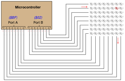
Note that a high state is required on one of port B’s pins to activate a row, and a low state is required on one of port A’s pins to activate a column, because the LED anodes connect to port A and the LED cathodes connect to port B.
Determine the hexadecimal codes we would need to output at ports A and B to energize the LED in the far lower-left corner of the 8 × 8 grid.
Port A =
Port B =
Reveal answerPort A = $FE
Port B = $80