Facebook
 Google
 GitHub
 Linkedin
Digital Circuits
Microcontroller Principles
20 questions By Tony R. Kuphaldt
-
Question 13 of 20
Many microcontrollers come equipped with a built-in PWM function, so that you do not have to code a custom PWM algorithm yourself. This fact points to the popularity of pulse-width modulation as a control scheme. Explain why PWM is so popular, and give a few practical examples of how it may be used.
Reveal answerI’ll let you do your own research for this question! The answer(s) is/are not hard to find.
Notes:Pulse-width modulation (PWM) is a very common and useful way of generating an analog output from a microcontroller (or other digital electronic circuit) capable only of “high” and “low” voltage level output. With PWM, time (or more specifically, duty cycle) is the analog domain, while amplitude is the digital domain. This allows us to “sneak” an analog signal through a digital (on-off) data channel.
-
Question 14 of 20
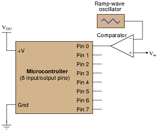
Pulse-width modulation (PWM) is not only useful for generating an analog output with a microcontroller, but it is also useful for receiving an analog input through a pin that only handles on-off (high-low) digital voltage levels. The following circuit takes an analog voltage signal in to a comparator, generates PWM, then sends that PWM signal to the input of a microcontroller:
Pseudocode listing Declare Pin0 as an input
Declare Last_Pin0 as a boolean variable
Declare Time_High as an integer variable
Declare Time_Low as an integer variable
Declare Duty_Cycle as a floating-point variable
Set Time_High and Time_Low both to zero
LOOP
Set Last_Pin0 equal to Pin0
If Pin0 is HIGH, increment Time_High by one
If Pin0 is LOW, increment Time_Low by one
If Last_Pin0 is not equal to Pin0, go to SUBROUTINE
ENDLOOP
SUBROUTINE
Set Duty_Cycle equal to (Time_High / (Time_High Time_Low))
Set Time_High and Time_Low both to zero
Return to calling loop
ENDSUBROUTINE
Explain how this program works. Hint: the Last_Pin0 boolean variable is used to detect when the state of Pin0 has changed from 0 to 1 or from 1 to 0.
Reveal answerThe trickiest part of this program is figuring out the Last_Pin0 variable’s function, and how it determines when to execute the subroutine. I strongly recommend you perform a “thought experiment” with a slow square-wave input signal to the microcontroller, examining how the Time_High and Time_Low variables become incremented with the square wave’s state.
Notes:Pulse-width modulation (PWM) is a very common and useful way of generating an analog output from a microcontroller (or other digital electronic circuit) capable only of “high” and “low” voltage level output. Here, we also see it used as a form of input signal modulation. With PWM, time (or more specifically, duty cycle) is the analog domain, while amplitude is the digital domain. This allows us to “sneak” an analog signal through a digital (on-off) data channel.
In case you’re wondering why I write in pseudocode, here are a few reasons:
- No prior experience with programming required to understand pseudocode
- It never goes out of style
- Hardware independent
- No syntax errors
If I had decided to showcase code that would actually run in a microcontroller, I would be dooming the question to obsolescence. This way, I can communicate the spirit of the program without being chained to an actual programming standard. The only drawback is that students will have to translate my pseudocode to real code that will actually run on their particular MCU hardware, but that is a problem guaranteed for some regardless of which real programming language I would choose.
Of course, I could have taken the Donald Knuth approach and invented my own (imaginary) hardware and instruction set . . .
-
Question 15 of 20
Digital computers communicate with external devices through ports: sets of terminals usually arranged in groups of 4, 8, 16, or more (4 bits = 1 nybble, 8 bits = 1 byte, 16 bits = 2 bytes). These terminals may be set to high or low logic states by writing a program for the computer that sends a numerical value to the port. For example, here is an illustration of a microcontroller being instructed to send the hexadecimal number F3 to port A and 2C to port B:
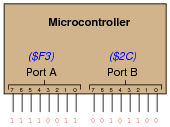
Suppose we wished to use the upper four bits of port A (pins 7, 6, 5, and 4) to drive the coils of a stepper motor in this eight-step sequence:
- Step 1:
- 0001
- Step 2:
- 0011
- Step 3:
- 0010
- Step 4:
- 0110
- Step 5:
- 0100
- Step 6:
- 1100
- Step 7:
- 1000
- Step 8:
- 1001
As each pin goes high, it drives a power MOSFET on, which sends current through that respective coil of the stepper motor. By following a “shift” sequence as shown, the motor will rotate a small amount for each cycle.
Write the necessary sequence of numbers to be sent to port A to generate this specific order of bit shifts, in hexadecimal. Leave the lower four bit of port A all in the low logic state.
Reveal answer- Step 1:
- 1016
- Step 2:
- 3016
- Step 3:
- 2016
- Step 4:
- 6016
- Step 5:
- 4016
- Step 6:
- C016
- Step 7:
- 8016
- Step 8:
- 9016
Follow-up question: write the same sequence in decimal rather than hexadecimal:
- Step 1:
- Step 2:
- Step 3:
- Step 4:
- Step 5:
- Step 6:
- Step 7:
- Step 8:
Notes:Although the root of this question is nothing more than binary-to-hexadecimal conversion, it also introduces students to the concept of controlling bit states in microcomputer ports by writing hex values. As such, this question is very practical!
In case students ask, let them know that a dollar sign prefix is sometimes used to denote a hexadecimal number. Other times, the prefix 0x is used (e.g., $F3 and 0xF3 mean the same thing).