Facebook
 Google
 GitHub
 Linkedin
Digital Circuits
Microcontroller Principles
20 questions By Tony R. Kuphaldt
-
Question 19 of 20
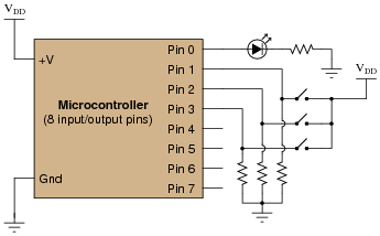
Examine the following schematic diagram and program listing (written in “pseudocode” rather than a formal programming language) to determine what type of basic logic function is being implemented in this microcontroller unit:
Pseudocode listing Declare Pin0 as an output
Declare Pin1, Pin2, and Pin3 as inputs
LOOP
IF Pin1 is HIGH, set Pin0 HIGH
ELSEIF Pin2 is HIGH, set Pin0 HIGH
ELSEIF Pin3 is HIGH, set Pin0 HIGH
ELSE set Pin0 LOW
ENDIF
ENDLOOP
Reveal answerThis microcontroller implements a 3-input logical OR function.
Notes:Although this logic function could have been implemented easier and cheaper in hard-wired (gate) logic, the purpose is to get students to think of performing logical operations by a sequenced set of instructions inside a programmable device (the MCU). This is a conceptual leap, basic but very important.
In case you’re wondering why I write in pseudocode, here are a few reasons:
- No prior experience with programming required to understand pseudocode
- It never goes out of style
- Hardware independent
- No syntax errors
If I had decided to showcase code that would actually run in a microcontroller, I would be dooming the question to obsolescence. This way, I can communicate the spirit of the program without being chained to an actual programming standard. The only drawback is that students will have to translate my pseudocode to real code that will actually run on their particular MCU hardware, but that is a problem guaranteed for some regardless of which real programming language I would choose.
Of course, I could have taken the Donald Knuth approach and invented my own (imaginary) hardware and instruction set . . .
-
Question 20 of 20
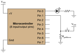
A student builds a microcontroller circuit to turn on an LED once for every five actuations of the input switch. The circuit is simple, with the microcontroller using a conditional loop to increment a variable each time the switch is pressed:
Pseudocode listing Declare Pin0 as an output
Declare Pin1 as an input
Declare X as an integer variable
LOOP
WHILE Pin1 is HIGH
Add 1 to X (X=X 1)
ENDWHILE
IF X is equal to 5, set Pin0 HIGH and set X to 0
ELSE set Pin0 LOW
ENDIF
ENDLOOP
Unfortunately, the program does not execute as planned. Instead of the LED coming on once every five switch actuations, it seems to come on randomly when the switch is released. Sometimes the LED turns on after the first switch actuation, while other times it takes more than five pushes of the switch to get it to turn on.
After some careful analysis, it occurs to the student that the problem lies in the WHILE loop. As the microcontroller is much faster than the human hand, that loop executes many times while the switch is being pressed rather than only once, meaning that the variable X counts from 0 to 5 many times around for each switch actuation. It is only by chance, then, that X will be equal to five after the WHILE loop exits.
What the student needs is for the switch to increment by 1 only for an off-to-on switch transition: at the positive edge of the input pulse. The problem is how to do this using programming.
Another student, when faced with the same problem, chose to solve it this way and it worked just fine:
Pseudocode listing Declare Pin0 as an output
Declare Pin1 as an input
Declare Switch as a Boolean (0 or 1) variable
Declare Last_Switch as a Boolean (0 or 1) variable
Declare X as an integer variable
LOOP
Set Last_Switch equal to Switch
Set Switch equal to Pin1
IF Switch = 1 and Last_Switch = 0 THEN add 1 to X (X=X 1)
ELSE do nothing to X
ENDIF
IF X is equal to 5, set Pin0 HIGH and set X to 0
ELSE set Pin0 LOW
ENDIF
ENDLOOP
Explain how this program successfully increments X only on each off-to-on transition of the pushbutton switch while the other program increments X rapidly during the entire duration the pushbutton switch is pressed.
Reveal answerThe key to understanding how this algorithm works is to realize the variable Last_Switch will always be one scan (loop execution) behind the variable Switch.
Challenge question: does it matter where in the program the following two lines go? Must they be placed immediately prior to the IF/THEN conditional statement?
Set Last_Switch equal to Switch
Set Switch equal to Pin1
Notes:This pulse-detection algorithm is very commonly used in programs dealing with real-world switch inputs. It performs in software what the pulse detection network does inside edge-triggered flip-flops, for the same effect: to initiate some kind of action only at the edge of a pulse signal.