Facebook
 Google
 GitHub
 Linkedin
Analog Integrated Circuits
OpAmp Oscillator Circuits
16 questions By Tony R. Kuphaldt
-
Question 10 of 16
This Wien bridge oscillator circuit is very sensitive to changes in the gain. Note how the potentiometer used in this circuit is the “trimmer” variety, adjustable with a screwdriver rather than by a knob or other hand control:
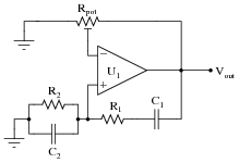
The reason for this choice in potentiometers is to make accidental changes in circuit gain less probable. If you build this circuit, you will see that tiny changes in this potentiometer’s setting make a huge difference in the quality of the output sine wave. A little too much gain, and the sine wave becomes noticeably distorted. Too little gain, and the circuit stops oscillating altogether!
Obviously, it is not good to have such sensitivity to minor changes in any practical circuit expected to reliably perform day after day. One solution to this problem is to add a limiting network to the circuit comprised of two diodes and two resistors:
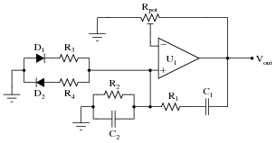
With this network in place, the circuit gain may be adjusted well above the threshold for oscillation (Barkhausen criterion) without exhibiting excessive distortion as it would have without the limiting network. Explain why the limiting network makes this possible.
Reveal answerThe limiting network attenuates the circuit gain as peak voltage begins to exceed 0.7 volts. This attenuation helps to prevent the opamp from clipping.
Follow-up question: what effect does this “limiting network” have on the purity of the oscillator’s output signal spectrum? In other words, does the limiting network increase or decrease the harmonic content of the output waveform?
Notes:This circuit is important for students to encounter, as it reveals a very practical limitation of the “textbook” version of the Wien bridge oscillator circuit. It is not enough that a circuit design work in ideal conditions - a practical circuit must be able to tolerate some variance in component values or else it will not operate reliably.
-
Question 11 of 16
This interesting opamp circuit produces true three-phase sinusoidal voltage waveforms, three of them to be exact:

With all the resistors and capacitors, you might have guessed this to be a phase-shift type of oscillator circuit, and you would be correct. Here, each parallel RC network provides 60 degrees of lagging phase shift to combine with the 180 degrees of phase shift inherent to the inverting amplifier configurations, yielding 120 degrees of shift per opamp stage.
Derive a formula solving for the operating frequency of this oscillator circuit, knowing that the impedance of each parallel RC network will have a phase angle of -60o. Also, determine where on this circuit you would obtain the three promised sine waves.
Reveal answerf = √3 2 πR CI’ll give you a hint on how to solve this problem: the admittance triangle for the parallel RC network will have angles of 60o, 30o, and of course 90o:

Notes:Unlike the multi-stage RC phase shift networks we are accustomed to seeing in discrete transistor phase-shift oscillator circuits, the phase shift networks in this oscillator circuit are much “purer,” being effectively isolated from each other by the current gain of each opamp. Here, each RC network provides the exact same amount of phase shift, and is not loaded by the RC network after it. This makes the math nice and easy (comparatively), and a good review of trigonometry!
This circuit came from the pages of one of my favorite opamp books, Applications Manual for Computing Amplifiers for Modeling, Measuring, Manipulation, and Much Else. Published by Philbrick Researches Inc. in 1966, it is a wonderfully written tour of “modern” operational amplifier applications and techniques. I only wish (truly) modern texts were written as well as this amazing booklet!
-
Question 12 of 16
Predict how the operation of this relaxation oscillator circuit will be affected as a result of the following faults. Consider each fault independently (i.e. one at a time, no multiple faults):
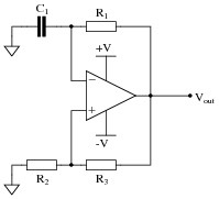
- Resistor R1 fails open:
- Solder bridge (short) across resistor R1:
- Capacitor C1 fails shorted:
- Solder bridge (short) across resistor R2:
- Resistor R3 fails open:
For each of these conditions, explain why the resulting effects will occur.
Reveal answer- Resistor R1 fails open: Opamp output saturates either positive or negative.
- Solder bridge (short) across resistor R1: Output voltage settles to 0 volts.
- Capacitor C1 fails shorted: Opamp output saturates either positive or negative.
- Solder bridge (short) across resistor R2: Output voltage settles to 0 volts.
- Resistor R3 fails open: Output voltage settles to 0 volts.
Notes:The purpose of this question is to approach the domain of circuit troubleshooting from a perspective of knowing what the fault is, rather than only knowing what the symptoms are. Although this is not necessarily a realistic perspective, it helps students build the foundational knowledge necessary to diagnose a faulted circuit from empirical data. Questions such as this should be followed (eventually) by other questions asking students to identify likely faults based on measurements.