
 Facebook
 Google
 GitHub
 Linkedin
Analog Integrated Circuits
OpAmp Oscillator Circuits
16 questions By Tony R. Kuphaldt
-
Question 7 of 16
Dual, or split, power supplies are very useful in opamp circuits because they allow the output voltage to rise above as well as sink below ground potential, for true AC operation. In some applications, though, it may not be practical or affordable to have a dual power supply to power your opamp circuit. In this event, you need to be able to figure out how to adapt your dual-supply circuit to single-supply operation.
A good example of such a challenge is the familiar opamp relaxation oscillator, shown here:

First, determine what would happen if we were to simply eliminate the negative portion of the dual power supply and try to run the circuit on a single supply ( V and Ground only):
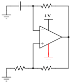
Then, modify the schematic so that the circuit will run as well as it did before with the dual supply.
Reveal answerHere is one solution:
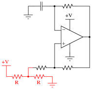
Here is another solution:
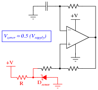
Follow-up question: now you just know what I’m going to ask next, don’t you? How do these modified circuits function?
Notes:Dual power supplies are a luxury in many real-life circumstances, and so your students will need to be able to figure out how to make opamps work in single-supply applications! Work with your students to analyze the function of the suggested solution circuit, to see how it is at once similar and different from its simpler, dual-supply forbear.
-
Question 8 of 16
Identify what type of oscillator circuit this is, and write an equation describing its operating frequency:

Reveal answerThis is a Wien bridge opamp oscillator, and its operating frequency is determined in the same way as a discrete-transistor Wien bridge oscillator circuit:
f = 1 2 πR CFollow-up question: based on your analysis of the circuit, how much phase shift does the Wien bridge circuit introduce into the feedback signal?
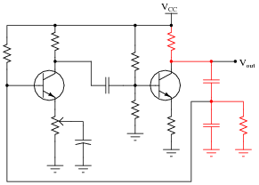
Notes:Unlike some discrete transistor oscillator circuits, this Wien bridge is a complete and full Wien bridge, and not a “half-bridge”. For an example of a Wien half-bridge circuit, look at this (the Wien bridge components shown in a different color):
-
Question 9 of 16
Explain the purpose of the tank circuit (L1 and C1) in the following oscillator circuit, and write an equation describing its operating frequency:

Reveal answerf = 1 2 π √ L1 C1Follow-up question: what do you suppose the purpose of the potentiometer is in this oscillator circuit?
Notes:Ask your students to describe the amount of phase shift the tank circuit provides to the feedback signal. Also, ask them to explain how the oscillator circuit’s natural frequency may be altered.
Note: potentiometer (voltage gain) adjustment is crucial for obtaining a good-quality sine wave from this type of circuit. If your students decide to build one, they should be aware that some experimentation will be required to get it to output good-quality sine waves!


