Facebook
 Google
 GitHub
 Linkedin
Analog Integrated Circuits
OpAmp Oscillator Circuits
16 questions By Tony R. Kuphaldt
-
Question 4 of 16
How many degrees of phase shift must the feedback circuit (the square box in this schematic) introduce to the signal in order for this non-inverting amplifier circuit to oscillate?
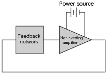
Reveal answerThe feedback network in this circuit must provide 360 degrees of phase shift, in order to sustain oscillations.
Notes:Ask your students to explain why the feedback network must provide 180 degrees of phase shift to the signal. Ask them to explain how this requirement relates to the need for regenerative feedback in an oscillator circuit.
-
Question 5 of 16
This is a very common opamp oscillator circuit, technically of the relaxation type:

Explain how this circuit works, and what waveforms will be measured at points A and B. Be sure to make reference to RC time constants in your explanation.
Reveal answerYou will measure a sawtooth-like waveform at point A, and a square wave at point B.
Challenge question: explain how you might go about calculating the frequency of such a circuit, based on what you know about RC time constant circuits. Assume that the opamp can swing its output rail-to-rail, for simplicity.
Notes:This circuit is best understood by building and testing. If you use large capacitor values and/or a large-value resistor in the capacitor’s current path, the oscillation will be slow enough to analyze with a voltmeter rather than an oscilloscope.
-
Question 6 of 16
A variation on the common opamp relaxation oscillator design is this, which gives it variable duty cycle capability:

Explain how this circuit works, and which direction the potentiometer wiper must be moved to increase the duty cycle (more time spent with the opamp output saturated at V and less time spent saturated at -V).
Reveal answerMove the wiper up to increase the duty cycle.
Notes:This circuit is best understood by building and testing. If you use large capacitor values and/or a large-value resistor in the capacitor’s current path, the oscillation will be slow enough to analyze with a voltmeter rather than an oscilloscope.
Incidentally, the Schottky diodes are not essential to this circuit’s operation, unless the expected frequency is very high. Really, the purpose of the Schottky diodes, with their low forward voltage drops (0.4 volts typical) and minimal charge storage, is to make the opamp’s job easier at every reversal of output polarity. Remember that this circuit is not exploiting negative feedback! Essentially, it is a positive feedback circuit, and every voltage drop and nonlinearity in the capacitor’s current path will have an effect on capacitor charging/discharging.