Facebook
 Google
 GitHub
 Linkedin
Discrete Semiconductor Devices and Circuits
Oscillator Circuits
49 questions By Tony R. Kuphaldt
-
Question 4 of 49
Define what an oscillator circuit is, using your own words. Give a few examples of oscillators at work in common devices and systems.
Reveal answerHere is a sample definition:
- An “oscillator” is a device that produces oscillations (back-and-forth) changes - usually an electronic circuit that produces AC - from a steady (DC) source of power.
I’ll let you determine some practical oscillator applications on your own!
Notes:Oscillators are nearly ubiquitous in a modern society. If your students’ only examples are electronic in nature, you may want to mention these mechanical devices:
- Pendulum clock mechanism
- Shaker (for sifting granular materials or mixing liquids such as paint)
- Whistle
- Violin string
-
Question 5 of 49
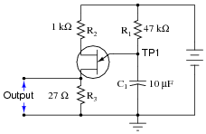
This relaxation oscillator circuit uses a resistor-capacitor combination (R1 - C1) to establish the time delay between output pulses:
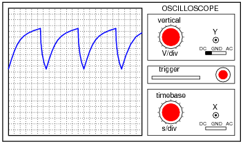
The voltage measured between TP1 and ground looks like this on the oscilloscope display:
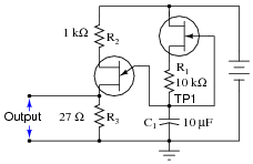
A slightly different version of this circuit adds a JFET to the capacitor’s charge current path:
Now, the voltage at TP1 looks like this:
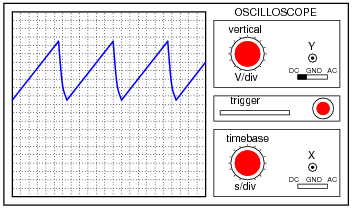
What function does the JFET perform in this circuit, based on your analysis of the new TP1 signal waveform? The straight-line charging voltage pattern shown on the second oscilloscope display indicates what the JFET is doing in this circuit.
Hint: you don’t need to know anything about the function of the unijunction transistor (at the circuit’s output) other than it acts as an on/off switch to periodically discharge the capacitor when the TP1 voltage reaches a certain threshold level.
Challenge question: write a formula predicting the slope of the ramping voltage waveform measured at TP1.
Reveal answerThe JFET in this circuit functions as a constant current regulator.
Answer to challenge question: Slope \(= \frac{dv}{dt} = \frac{I_D}{C}\)
Notes:Ask your students how they would know to relate “constant current” to the peculiar charging action of this capacitor. Ask them to explain this mathematically.
Then, ask them to explain exactly how the JFET works to regulate charging current.
Note: the schematic diagram for this circuit was derived from one found on page 958 of John Markus’
Guidebook of Electronic Circuits, first edition. Apparently, the design originated from a Motorola publication on using unijunction transistors (“Unijunction Transistor Timers and Oscillators,” AN-294, 1972).
-
Question 6 of 49
This circuit shown here is for a timing light: a device that uses a pulsed strobe lamp to “freeze” the motion of a rotating object.
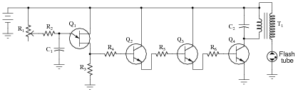
Which component(s) in this circuit form the oscillator section? What type of oscillator is used in this circuit? Which component values have a direct influence on the frequency of the flash tube’s output?
Reveal answerThe heart of the oscillator circuit is unijunction transistor Q1. Together with some other components (I’ll let you figure out which!), this transistor forms a relaxation oscillator circuit. R1, R2, and C1 have direct influence over the oscillation frequency.
Challenge question: what purpose does resistor R2 serve? It would seem at first glance that it serves no useful purpose, as potentiometer R1 is capable of providing any desired amount of resistance for the RC time constant circuit on its own - R2‘s resistance is simply added to it. However, there is an important, practical reason for including R2 in the circuit. Explain what that reason is.
Notes:Ask your students to explain what the other transistors do in this circuit. If time permits, explore the operation of the entire circuit with your students, asking them to explain the purpose and function of all components in it.
After they identify which components control the frequency of oscillation, ask them to specifically identify which direction each of those component values would need to be changed in order to increase (or decrease) the flash rate.