Facebook
 Google
 GitHub
 Linkedin
AC Electric Circuits
Passive Integrator and Differentiator Circuits
25 questions By Tony R. Kuphaldt
-
Question 19 of 25
∫f(x) dx Calculus alert!
In calculus, differentiation is the inverse operation of something else called integration. That is to say, differentiation “un-does” integration to arrive back at the original function (or signal). To illustrate this electronically, we may connect a differentiator circuit to the output of an integrator circuit and (ideally) get the exact same signal out that we put in:
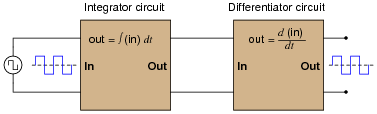
Based on what you know about differentiation and differentiator circuits, what must the signal look like in between the integrator and differentiator circuits to produce a final square-wave output? In other words, if we were to connect an oscilloscope in between these two circuits, what sort of signal would it show us?
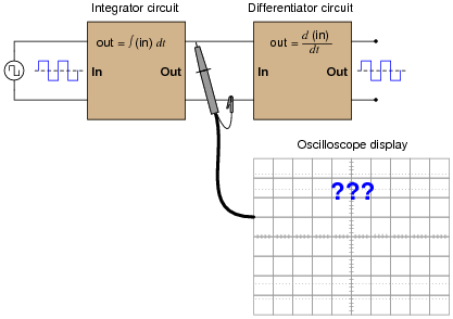
Reveal answer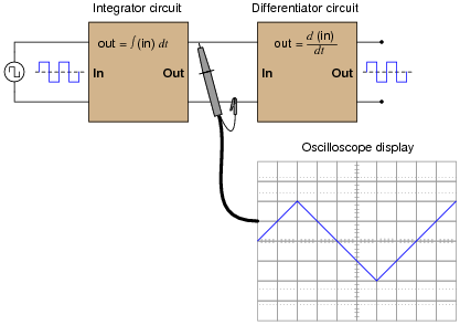
Follow-up question: what do the schematic diagrams of passive integrator and differentiator circuits look like? How are they similar to one another and how do they differ?
Notes:This question introduces students to the concept of integration, following their prior familiarity with differentiation. Since they should already be familiar with other examples of inverse mathematical functions (arcfunctions in trigonometry, logs and powers, squares and roots, etc.), this should not be too much of a stretch. The fact that we may show them the cancellation of integration with differentiation should be proof enough.
In case you wish to demonstrate this principle “live” in the classroom, I suggest you bring a signal generator and oscilloscope to the class, and build the following circuit on a breadboard:
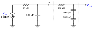
The output is not a perfect square wave, given the loading effects of the differentiator circuit on the integrator circuit, and also the imperfections of each operation (being passive rather than active integrator and differentiator circuits). However, the wave-shapes are clear enough to illustrate the basic concept.
-
Question 20 of 25
When a circuit designer needs a circuit to provide a time delay, he or she almost always chooses an RC circuit instead of an LR circuit. Explain why this is.
Reveal answerCapacitors are generally cheaper and easier to work with than inductors for making time delay circuits.
Notes:The answer given here is purposely minimal. You should ask your students to give responses more thoughtful than this! Ask them why capacitors are cheaper than inductors. Ask them to explain what is meant by “easier to work with,” in technical terms.
-
Question 21 of 25
An LR differentiator circuit is used to convert a triangle wave into a square wave. One day after years of proper operation, the circuit fails. Instead of outputting a square wave, it outputs a triangle wave, just the same as the waveform measured at the circuit’s input. Determine what the most likely component failure is in the circuit.
Reveal answerThe inductor is failed open.
Follow-up question: this is not the only possible failure, but it is the most likely. Explain what the other failure(s) could be, and also why the one given here is most likely.
Notes:There are only two components in this circuit, so determining possible failures should not be a problem at all. To distinguish between the inductor having failed versus the resistor having failed, one needs to know which type of component failures are more likely (and why!).