Facebook
 Google
 GitHub
 Linkedin
Digital Circuits
Performance-Based Assessments for Digital Circuit Competencies
43 questions By Tony R. Kuphaldt
-
Question 28 of 43
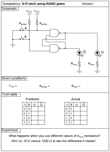
Reveal answerUse circuit simulation software to verify your predicted and actual truth tables.
Notes:Pushbutton switches are recommended over toggle switches for demonstrating a latch circuit. When the contacts are momentary, the latching characteristics of the circuit becomes more evident to see.
I have intentionally requested students try different resistance values for Rlimit so they may see the effects of gate output loading, and the importance of proper logic level voltages. Students should try undersized resistors (10 Ω, perhaps) on both LEDs to generate this problem, and then use oversized resistors (1000 Ω, perhaps) to make the problem go away. Large-valued limiting resistors will cause the LEDs to be dim, but will also restore workable voltage levels so that “high” output states are actually interpreted as “high” when fed back to the gate inputs.
-
Question 29 of 43

Reveal answerUse circuit simulation software to verify your predicted and actual truth tables.
Notes:Pushbutton switches are recommended over toggle switches for demonstrating a latch circuit. When the contacts are momentary, the latching characteristics of the circuit becomes more evident to see.
If students use LEDs to indicate the Q and \(\bar{Q}\) output states, they may experience trouble with the circuit not latching as it should. This is an excellent example of gate output loading, and the importance of proper logic level voltages. If such problems are encountered, advise the student(s) to use over-sized (too large) LED dropping resistors. This will cause the LEDs to be dim, but restore workable voltage levels so that “high” output states are actually interpreted as “high” when fed back to the gate inputs.
-
Question 30 of 43

Reveal answerUse circuit simulation software to verify your predicted and actual truth tables.
Notes:In this activity, students are asked to figure out how to wire the inputs of the J-K flip-flop circuit, and also how to demonstrate the three modes (Set, Reset, and Toggle). Students will have to properly set up their square-wave signal generators to create a workable clock pulse. This not only means a clock pulse at the correct voltage levels, but also one that is slow enough to allow them to clearly see the toggling of the flip-flop.
A great thing to do here is have students use a logic probe to sense the clock pulse and compare that frequency with the blinking of the Q and \(\bar{Q}\) LEDs.