Facebook
 Google
 GitHub
 Linkedin
Digital Circuits
Performance-Based Assessments for Digital Circuit Competencies
43 questions By Tony R. Kuphaldt
-
Question 10 of 43
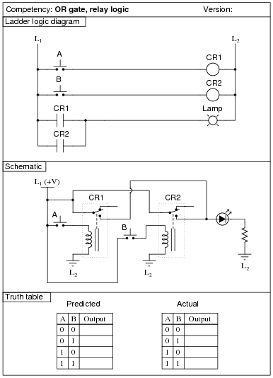
Reveal answerUse circuit simulation software to verify your predicted and actual truth tables.
Notes:The transition from ladder logic diagram to actual relay wiring is a confusing one for many students. This is what I consider to be the most significant learning objective of this exercise: figuring out how to build the circuit, not necessarily understanding the logical function of it.
-
Question 11 of 43
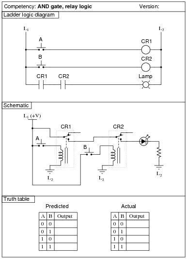
Reveal answerUse circuit simulation software to verify your predicted and actual truth tables.
Notes:The transition from ladder logic diagram to actual relay wiring is a confusing one for many students. This is what I consider to be the most significant learning objective of this exercise: figuring out how to build the circuit, not necessarily understanding the logical function of it.
-
Question 12 of 43

Reveal answerUse circuit simulation software to verify your predicted and actual truth tables.
Notes:The purpose of this exercise is for students to research what type of IC this is (from the given part number for U1), its pinout, and then predict and prove its operation using truth tables to document the results. You, as the instructor, may select any 14-pin CMOS or TTL logic IC that you wish. Students are to draw the logic gate symbol within the rectangle of U1, then connect that symbol to the input switches and output LED.
It needs to be understood that the “0” and “1” states are defined by voltage levels with respect to ground, and not by switch actuation. Many students assume an actuated (pushed) switch is a “1” input and a de-actuated (un-pushed) switch is a “0” input. Not necessarily so! In this circuit, the switches are connecting inputs to ground. This means a closed (actuated) switch provides a low (0) input state, while an open (un-actuated) switch provides a high (1) input state.