Facebook
 Google
 GitHub
 Linkedin
Discrete Semiconductor Devices and Circuits
Power Conversion Circuits
30 questions By Tony R. Kuphaldt
-
Question 28 of 30
Describe the purpose and function of this circuit:
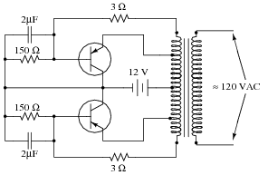
The 120 volt AC output provided by this circuit is definitely not sinusoidal, and the circuit’s frequency varies with load. Can you think of any way(s) to improve these aspects of the circuit (you need not show details of your design modifications)?
Reveal answerThis is an inverter circuit.
Be prepared to explain what each of the transistors does, and how the transformer is able to function with DC power on its primary winding.
Notes:This particular schematic was derived from a Triad brand transformer application, part number TY-75A. Recommended transistors were Delco 2N278, Bendix 2N678, Clevite 2N1146, and Delco 2N173. Slight variations in resistor and capacitor sizes may result in better performance. The 3 Ω resistors should have power ratings of at least 5 watts each, and the 150 Ω resistors should be rated for at least 20 watts each.
-
Question 29 of 30
∫f(x) dx Calculus alert!
Electronic power conversion circuits known as inverters convert DC into AC by using transistor switching elements to periodically reverse the polarity of the DC voltage. Usually, inverters also increase the voltage level of the input power by applying the switched-DC voltage to the primary winding of a step-up transformer. You may think of an inverter’s switching electronics as akin to double-pole, double-throw switch being flipped back and forth many times per second:
The first commercially available inverters produced simple square-wave output:
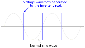
However, this caused problems for most power transformers designed to operate on sine-wave AC power. When powered by the square-wave output of such an inverter, most transformers would saturate due to excessive magnetic flux accumulating in the core at certain points of the waveform’s cycle. To describe this in the simplest terms, a square wave possesses a greater volt-second product than a sine wave with the same peak amplitude and fundamental frequency.
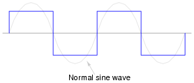
This problem could be avoided by decreasing the peak voltage of the square wave, but then some types of powered equipment would experience difficulty due to insufficient (maximum) voltage:
A workable solution to this dilemma turned out to be a modified duty cycle for the square wave:
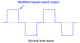
Calculate the fraction of the half-cycle for which this modified square wave is “on,” in order to have the same volt-second product as a sine wave for one-half cycle (from 0 to π radians):
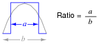
Hint: it is a matter of calculating the respective areas underneath each waveform in the half-cycle domain.
Reveal answerFraction = \(\frac{2}{\pi} \approx 0.637\)
Challenge question: prove that the duty cycle fraction necessary for the square wave to have the same RMS value as the sine wave is exactly 1/2. Hint: the volts-squared-second product of the two waveforms must be equal for their RMS values to be equal!
Notes:This problem is a great example of how integration is used in a very practical sense. Even if your students are unfamiliar with calculus, they should at least be able to grasp the concept of equal volt-second products for the two waveforms, and be able to relate that to the amount of magnetic flux accumulating in the transformer core throughout a cycle.
-
Question 30 of 30
A common topology for DC-AC power converter circuits uses a pair of transistors to switch DC current through the center-tapped winding of a step-up transformer, like this:
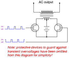
In order for this form of circuit to function properly, the transistor “firing” signals must be precisely synchronized to ensure the two are never turned on simultaneously. The following schematic diagram shows a circuit to generate the necessary signals:

Explain how this circuit works, and identify the locations of the frequency control and pulse duty-cycle control potentiometers.
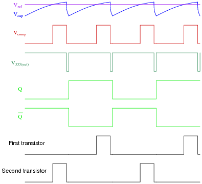
Reveal answerA timing diagram is worth a thousand words:
- •
- Vref = DC reference voltage set by duty cycle potentiometer
- •
- Vcap = Voltage measured at top terminal of the 555’s capacitor
- •
- Vcomp = Comparator output voltage
- •
- V555(out) = 555 timer output voltage
- •
- Q = Noninverted output of J-K flip-flop
- •
- \(\overline{Q}\) = Inverted output of J-K flip-flop
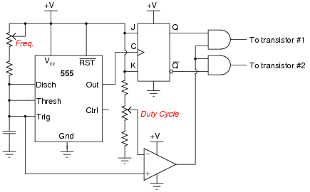
Follow-up question: which direction would you have to move the frequency potentiometer to increase the output frequency of this circuit? Which direction would you have to move the duty cycle potentiometer to increase that as well?
Challenge question: suppose you were prototyping this circuit without the benefit of an oscilloscope. How could you test the circuit to ensure the final output pulses to the transistors are never simultaneously in the “high” logic state? Assume you had a parts assortment complete with light-emitting diodes and other passive components.
Notes:This question is an exercise in schematic diagram and timing diagram interpretation. By the way, I have built and tested this circuit and I can say it works very well.