Facebook
 Google
 GitHub
 Linkedin
Discrete Semiconductor Devices and Circuits
Power Conversion Circuits
30 questions By Tony R. Kuphaldt
-
Question 16 of 30
The output voltage of an inverting converter circuit is a function of the input voltage and the duty cycle of the switching signal, represented by the variable D (ranging in value from 0% to 100%), where \(D = \frac{t_{on}}{t_{on}+t_{off}}\):
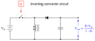
Based on this mathematical relationship, calculate the output voltage of this converter circuit at these duty cycles, assuming an input voltage of 40 volts:
- D = 0% ; Vout =
- D = 25% ; Vout =
- D = 50% ; Vout =
- D = 75% ; Vout =
- D = 100% ; Vout =
Reveal answer- D = 0% ; Vout = 0 volts
- D = 25% ; Vout = 13.3 volts
- D = 50% ; Vout = 40 volts
- D = 75% ; Vout = 120 volts
- D = 100% ; Vout = 0 volts
Notes:The calculations for this circuit should be straightforward, except for the last calculation with a duty cycle of D = 100%. Here, students must take a close look at the circuit and not just follow the formula blindly.
Note that the switching element in the schematic diagram is shown in generic form. It would never be a mechanical switch, but rather a transistor of some kind.
-
Question 17 of 30
The output voltage of a Cuk converter circuit (named after the engineer who invented it) is a function of the input voltage and the duty cycle of the switching signal, represented by the variable D (ranging in value from 0% to 100%), where \(D = \frac{t_{on}}{t_{on}+t_{off}}\):
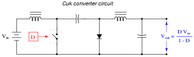
Based on this mathematical relationship, calculate the output voltage of this converter circuit at these duty cycles, assuming an input voltage of 25 volts:
- D = 0% ; Vout =
- D = 25% ; Vout =
- D = 50% ; Vout =
- D = 75% ; Vout =
- D = 100% ; Vout =
Reveal answer- D = 0% ; Vout = 0 volts
- D = 25% ; Vout = 8.33 volts
- D = 50% ; Vout = 25 volts
- D = 75% ; Vout = 75 volts
- D = 100% ; Vout = 0 volts
Notes:The calculations for this circuit should be straightforward, except for the last calculation with a duty cycle of D = 100%. Here, students must take a close look at the circuit and not just follow the formula blindly.
Note that the switching element in the schematic diagram is shown in generic form. It would never be a mechanical switch, but rather a transistor of some kind.
Astute students will note that there is no difference between the standard inverting converter circuit and the Cuk design, as far as output voltage calculations are concerned. This, however, does not mean the two circuits are equivalent in all ways! One definite advantage of the Cuk converter over the standard inverting converter is that the Cuk’s input current never goes to zero during the switch’s “off” cycle. This makes the Cuk circuit a “quieter” load as seen from the power source. Both inverting and buck converter circuits create a lot of electrical noise on the supply side if their inputs are unfiltered!
-
Question 18 of 30
The following equations solve for the output voltage of various switching converter circuits (unloaded), given the switch duty cycle D and the input voltage:
$$V_{out}=DV_{in} \ \ \ \ \ \ \ \ \ \ (Buck \ \ converter \ \ circuit)$$
$$V_{out}=\frac{V_{in}}{1-D} \ \ \ \ \ \ \ \ \ \ (Boost \ \ converter \ \ circuit)$$
$$V_{out}=\frac{DV_{in}}{1-D} \ \ \ \ \ \ \ \ \ \ (Inverting \ \ or \ \ Cuk \ \ converter \ \ circuit)$$
Manipulate each of these equations to solve for duty cycle (D) in terms of the input voltage (Vin) and desired output voltage (Vout). Remember that duty cycle is always a quantity between 0 and 1, inclusive.
Reveal answer$$D=\frac{V_{out}}{V_{in}} \ \ \ \ \ \ \ \ \ \ (Buck \ \ converter \ \ circuit)$$
$$D=1-(\frac{V_{in}}{V_{out}}) \ \ \ \ \ \ \ \ \ \ (Boost \ \ converter \ \ circuit)$$
$$D=\frac{V_{out}}{V_{in}+V_{out}} \ \ \ \ \ \ \ \ \ \ (Inverting \ \ or \ \ Cuk \ \ converter \ \ circuit)$$
Notes:Given the equations for these converter circuit types solving for output voltage in terms of input voltage and duty cycle D, this question is nothing more than an exercise in algebraic manipulation.
Note to your students that all of these equations assume a condition of zero load on the converter circuit. When loads are present, of course, the output voltage will not be the same as what is predicted by these neat, simple formulae. Although these DC-DC power converter circuits are commonly referred to as “regulators,” it is somewhat misleading to do so because it falsely implies a capacity for self-correction of output voltage. Only when coupled to a feedback control network are any of these converter circuits capable of actually regulating output voltage to a set value.