Facebook
 Google
 GitHub
 Linkedin
Discrete Semiconductor Devices and Circuits
Power Conversion Circuits
30 questions By Tony R. Kuphaldt
-
Question 13 of 30
Shown here are two voltage-reducing circuits: both reducing a supply voltage of 13.5 volts down to 5 volts for a load.
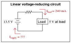
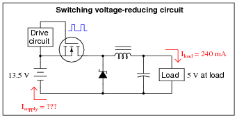
Calculate the average supply current (Isupply) for both of these circuits. Assume that the switching circuit has negligible power losses in the transistor, inductor, capacitor, and diode. If the 13.5 volt source were an electrochemical battery, which battery would last longer powering the same load?
Reveal answerThe battery supplying the linear circuit must source 240 mA, while the battery supplying the switching circuit must only source an average current of 88.9 mA.
Follow-up question: calculate the power efficiency of the linear circuit, and comment on why it is so different from the switching circuit.
Notes:Explain to your students that switching power conversion circuits are very efficient: typically 85 to 95 percent! It should be rather obvious which battery will last longer, and why. This is precisely why switching regulator circuits (DC-DC converters with a feedback network to stabilize output voltage) are used in place of linear regulator circuits (zener diode based) in many battery-powered electronic applications.
In essence, switching converter circuits act like DC transformers, able to step voltage down (or up), with current inversely proportional. Of course, the Law of Energy Conservation holds for switching circuits just as it does for transformers, and students may find this Law the easiest way to perform supply/load current calculations knowing the supply and load voltages:
Pout ≈ Pin VinIin ≈ VoutIout If time permits, you might want to show your students a datasheet for a power converter controller, showing them how integrated circuits exist to precisely control the switching of MOSFETs for power converter circuits just like this.
-
Question 14 of 30
The output voltage of a buck converter circuit is a function of the input voltage and the duty cycle of the switching signal, represented by the variable D (ranging in value from 0% to 100%), where \(D=\frac{t_{on}}{t_{on}+t_{off}}\):
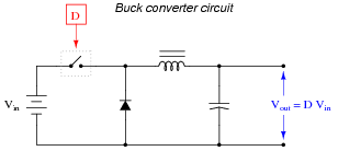
Based on this mathematical relationship, calculate the output voltage of this converter circuit at these duty cycles, assuming an input voltage of 40 volts:
- D = 0% ; Vout =
- D = 25% ; Vout =
- D = 50% ; Vout =
- D = 75% ; Vout =
- D = 100% ; Vout =
Reveal answer- D = 0% ; Vout = 0 volts
- D = 25% ; Vout = 10 volts
- D = 50% ; Vout = 20 volts
- D = 75% ; Vout = 30 volts
- D = 100% ; Vout = 40 volts
Notes:The calculations for this circuit should be very straightforward.
Note that the switching element in the schematic diagram is shown in generic form. It would never be a mechanical switch, but rather a transistor of some kind.
-
Question 15 of 30
The output voltage of a boost converter circuit is a function of the input voltage and the duty cycle of the switching signal, represented by the variable D (ranging in value from 0% to 100%), where D = [(ton)/(ton toff)]:
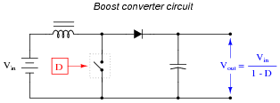
Based on this mathematical relationship, calculate the output voltage of this converter circuit at these duty cycles, assuming an input voltage of 40 volts:
- D = 0% ; Vout =
- D = 25% ; Vout =
- D = 50% ; Vout =
- D = 75% ; Vout =
- D = 100% ; Vout =
Reveal answer- D = 0% ; Vout = 40 volts
- D = 25% ; Vout = 53.3 volts
- D = 50% ; Vout = 80 volts
- D = 75% ; Vout = 160 volts
- D = 100% ; Vout = 0 volts
Notes:The calculations for this circuit should be straightforward, except for the last calculation with a duty cycle of D = 100%. Here, students must take a close look at the circuit and not just follow the formula blindly.
Note that the switching element in the schematic diagram is shown in generic form. It would never be a mechanical switch, but rather a transistor of some kind.