Facebook
 Google
 GitHub
 Linkedin
Discrete Semiconductor Devices and Circuits
Power Conversion Circuits
30 questions By Tony R. Kuphaldt
-
Question 22 of 30
A “boost” switching converter operating at 80% efficiency delivers 178 volts at 1 amp to a DC load. Calculate the input voltage if the input current is 11 amps.
Reveal answerVinput = 20.2 volts
Notes:Calculations involving energy efficiency seem very confusing to some students. One principle that I often remind my students of is the Law of Energy Conservation, which prohibits any circuit from outputting more energy (or power) than it takes in. All too often, students mis-calculate in problems such as these, ending up with output powers greater than input powers!
Discuss problem-solving techniques, soliciting input from your students. Ideally, have individuals or groups present their techniques to the class as a whole, so you may observe their thinking processes and so that other students may learn how to become better problem-solvers.
-
Question 23 of 30
The output voltage of a buck converter is a direct function of the switching transistor’s duty cycle. Specifically, \(V_{out} = V_{in}(\frac{t_{on}}{t_{total}})\). Explain how the following PWM control circuit regulates the output voltage of the buck converter:
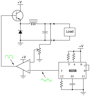
Reveal answerIf the load (output) voltage sags, the PWM circuit generates an output signal with a greater duty cycle, which then drives the power transistor to provide more voltage to the load.
Follow-up question: what is the purpose of the potentiometer in this circuit?
Notes:Here, students see a PWM control circuit coupled with a buck converter to provide voltage-regulated power conversion. Ask them what form of feedback (positive or negative?) is used in this circuit to regulate the output voltage at a steady value.
Let your students know that the PWM and feedback functions for switching regulator circuits are often provided in a single, application-specific integrated circuit rather than by a collection of discrete components and IC’s as shown in the question.
-
Question 24 of 30
The energy efficiency (η) of switching converter circuits typically remains fairly constant over a wide range of voltage conversion ratios. Describe how a switching regulator circuit (controlling load voltage to a pre-set value) “appears” to a power source of changing voltage if the regulator’s load is constant. In other words, as the input voltage changes, what does the input current do?
Reveal answerThe input current of a switching regulator is inversely proportional to the input voltage when powering a constant load, appearing as a negative impedance to the power source.
Notes:“Negative impedance” and “negative resistance” are phrases that may not be addressed very often in a basic electronics curriculum, but they have important consequences. If students experience difficulty understanding what the meaning of “negative” impedance is, remind them of this mathematical definition for impedance:
$$Z=\frac{dV}{dI}$$
One of the unintended (and counter-intuitive) consequences of a circuit element with negative impedance can be oscillation, especially when the input power circuit happens to contain substantial inductance.