
 Facebook
 Google
 GitHub
 Linkedin
Discrete Semiconductor Devices and Circuits
Power Conversion Circuits
30 questions By Tony R. Kuphaldt
-
Question 10 of 30
Predict how the operation of this buck converter circuit will be affected as a result of the following faults. Consider each fault independently (i.e. one at a time, no multiple faults):

- Drive circuit fails with a constant “low” (0 volts) output signal:
- Drive circuit fails with a constant “high” ( V) output signal:
- Diode fails shorted:
- Inductor fails open:
- Capacitor fails shorted:
For each of these conditions, explain why the resulting effects will occur.
Reveal answer- Drive circuit fails with a constant “low” (0 volts) output signal: Output voltage falls to zero after capacitor discharges.
- Drive circuit fails with a constant “high” ( V) output signal: Output voltage rises to become approximately equal to Vin.
- Diode fails shorted: Output voltage falls to zero, then transistor fails due to overheating.
- Inductor fails open: Output voltage falls to zero after capacitor discharges.
- Capacitor fails shorted: Output voltage falls to zero immediately.
Notes:The purpose of this question is to approach the domain of circuit troubleshooting from a perspective of knowing what the fault is, rather than only knowing what the symptoms are. Although this is not necessarily a realistic perspective, it helps students build the foundational knowledge necessary to diagnose a faulted circuit from empirical data. Questions such as this should be followed (eventually) by other questions asking students to identify likely faults based on measurements.
-
Question 11 of 30
Predict how the operation of this boost converter circuit will be affected as a result of the following faults. Consider each fault independently (i.e. one at a time, no multiple faults):
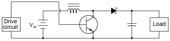
- Drive circuit fails with a constant “low” (0 volts) output signal:
- Drive circuit fails with a constant “high” ( V) output signal:
- Diode fails shorted:
- Inductor fails open:
- Capacitor fails shorted:
For each of these conditions, explain why the resulting effects will occur.
Reveal answer- Drive circuit fails with a constant “low” (0 volts) output signal: Output voltage rises to become approximately equal to Vin.
- Drive circuit fails with a constant “high” ( V) output signal: Output voltage falls to zero after capacitor discharges.
- Diode fails shorted: Output voltage exhibits very large “ripple” as the voltage repeatedly falls to zero and spikes back up each drive cycle, transistor may fail due to overheating.
- Inductor fails open: Output voltage falls to zero after capacitor discharges.
- Capacitor fails shorted: Output voltage falls to zero immediately.
Notes:The purpose of this question is to approach the domain of circuit troubleshooting from a perspective of knowing what the fault is, rather than only knowing what the symptoms are. Although this is not necessarily a realistic perspective, it helps students build the foundational knowledge necessary to diagnose a faulted circuit from empirical data. Questions such as this should be followed (eventually) by other questions asking students to identify likely faults based on measurements.
-
Question 12 of 30
So-called linear regulator circuits work by adjusting either a series resistance or a shunt resistance to maintain output voltage at some fractional value of input voltage:
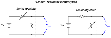
Typically, these variable resistances are provided by transistors rather than actual rheostats, which would have to be manually controlled.
Explain why a switching regulator circuit would perform the same task as a linear regulator circuit at a much greater efficiency. Also, identify which type(s) of switching regulator circuit would be best suited for the task of reducing an input voltage to a lesser output voltage.
Reveal answerA buck regulator circuit functions in nearly the same manner as a transformer: stepping voltage down while stepping current up. Ideally, switching regulator circuits waste zero energy, unlike (resistive) linear regulator circuits.
Follow-up question: which type of linear regulator circuit does the traditional zener diode voltage regulator belong to, series or shunt?
Notes:In the process of analyzing switching regulator functionality, it is easy for students to overlook the purpose for why they exist at all. Discuss the importance of power conversion efficiency, especially for electronic applications that are battery powered.
An important point to emphasize in this question is that most of the switching “regulator” circuits first shown to students are not actually regulators at all, but merely converters. A switching converter circuit does not become a regulator circuit until a feedback control is added. Such controls are usually too complex to introduce at the very beginning, so they are typically omitted for simplicity’s sake. However, students should realize the difference between a switching regulator circuit and a mere switching converter circuit, lest they believe the converter to be capable of more than it is.


