Facebook
 Google
 GitHub
 Linkedin
Discrete Semiconductor Devices and Circuits
Power Conversion Circuits
30 questions By Tony R. Kuphaldt
-
Question 4 of 30
This circuit uses an 8038 waveform generator IC (integrated circuit) to produce a “sawtooth” waveform, which is then compared against a variable DC voltage from a potentiometer:
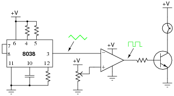
The result is a pulse waveform to the base of the power transistor, of the same frequency as the sawtooth waveform. Normally in circuits such as this, the frequency is at least several hundred Hertz.
Explain what happens to the brightness of the lamp when the potentiometer wiper is moved closer to V, and when it is moved closer to ground.
Reveal answerThe lamp glows brighter as the duty cycle of the pulse waveform increases, and visa-versa.
Notes:This question is a good review of comparator operation, and it introduces the concept of duty cycle, if your students have not encountered it before. Ask your students to explain how and why the duty cycle changes as the potentiometer wiper is moved. Ask them to explain why the lamp’s brightness changes with duty cycle, and whether or not this is an efficient method of power control.
-
Question 5 of 30
This circuit generates a pulse of DC voltage sufficient to energize the neon lamp, every time the switch is opened:
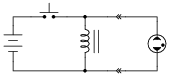
Describe the principle of operation for this simple circuit, and also how it could be modified to produce continuous high-voltage DC power.
Hint: how does a common AC-DC power supply circuit convert pulses of rectified DC into a relatively “smooth” DC output?
Reveal answer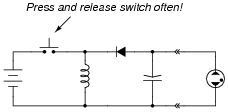
Follow-up question: how would you recommend we “automate” this circuit so that a person does not have to keep pressing and releasing the switch for it to generate a continuous DC output voltage?
Notes:Ask your students to explain their solutions for “automating” the switch’s action. Prepare yourself for some creative answers!
-
Question 6 of 30
The schematic diagram shown here is for a “buck” converter circuit, a type of DC-DC “switching” power conversion circuit:
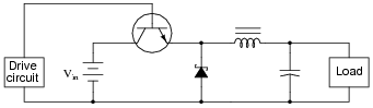
In this circuit, the transistor is either fully on or fully off; that is, driven between the extremes of saturation or cutoff. By avoiding the transistor’s “active” mode (where it would drop substantial voltage while conducting current), very low transistor power dissipations can be achieved. With little power wasted in the form of heat, “switching” power conversion circuits are typically very efficient.
Trace all current directions during both states of the transistor. Also, mark the inductor’s voltage polarity during both states of the transistor.
Reveal answer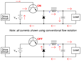
Follow-up question: how does the load voltage of this converter relate to the supply (battery) voltage? Does the load receive more or less voltage than that provided by the battery?
Challenge question: why do you suppose a Schottky diode is used in this circuit, as opposed to a regular (PN) rectifying diode?
Notes:Ask your students why they think this circuit is called a buck converter. “Buck” usually refers to something that is in opposition. What is being opposed in this circuit?