Facebook
 Google
 GitHub
 Linkedin
Analog Integrated Circuits
Precise Diode Circuits
14 questions By Tony R. Kuphaldt
-
Question 7 of 14
Predict how the operation of this precision rectifier circuit will be affected as a result of the following faults. Consider each fault independently (i.e. one at a time, no multiple faults):
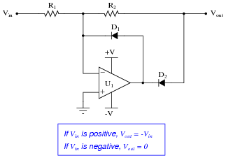
- Resistor R1 fails open:
- Resistor R2 fails open:
- Diode D1 fails open:
- Diode D2 fails open:
For each of these conditions, explain why the resulting effects will occur.
Reveal answer- Resistor R1 fails open: Vout becomes equal to 0 volts all the time.
- Resistor R2 fails open: Vout saturates negative when Vin is positive, and Vout floats up to 1.4 volts when Vin is negative (depending on how the output is loaded by another circuit).
- Diode D1 fails open: Normal operation when Vin is positive (Vout = − Vin), Vout = Vin when Vin is negative (full-wave, inverted rectification!).
- Diode D2 fails open: Normal operation when Vin is negative (Vout = 0 volts), Vout = Vin when Vin is positive (half-wave, non-inverted rectification!).
Notes:The purpose of this question is to approach the domain of circuit troubleshooting from a perspective of knowing what the fault is, rather than only knowing what the symptoms are. Although this is not necessarily a realistic perspective, it helps students build the foundational knowledge necessary to diagnose a faulted circuit from empirical data. Questions such as this should be followed (eventually) by other questions asking students to identify likely faults based on measurements.
-
Question 8 of 14
The following circuit is sometimes referred to as a polarity separator. Invent some test conditions you would use to “prove” the operation of the circuit, then analyze the circuit under those imagined conditions and see what the results are:

Explain what each output does in this “polarity separator” circuit for any given input voltage.
Reveal answerThe Vout1 output is the inverse (negative) of any positive input voltage, while the Vout2 output is the inverse (positive) of any negative input voltage.
Notes:This circuit is a good introduction to the full-wave precision rectifier circuit, although its operation there is a bit more difficult to understand than it is here.
-
Question 9 of 14
Determine the output voltage of this circuit for two different input voltage values: 4 volts, and -4 volts. Determine the voltage at each and every node with respect to ground as part of your analysis:

Based on this data (and any other input conditions you wish to test this circuit under), describe what the function of this circuit is.
Reveal answer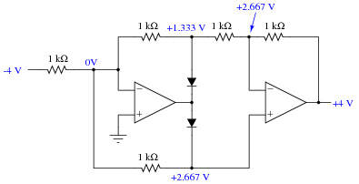
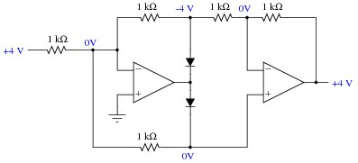
This circuit is a precision full-wave rectifier.
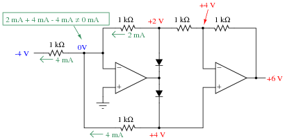
Notes:It is much easier to analyze the behavior of this circuit with a positive input voltage than it is to analyze it with a negative input voltage! There is a tendency for students to reach this conclusion when analyzing the circuit’s behavior with a negative input voltage:

The error seems reasonable until an analysis of current is made. If these voltages were true, Kirchhoff’s Current Law would be violated at the first opamp’s virtual ground: