Facebook
 Google
 GitHub
 Linkedin
Building a 5 V Single-Supply Electret Microphone Preamp
This project brief describes how to build a compact, single-supply preamplifier module that converts the output of an electret microphone into a usable line-level audio signal.
Electret microphones are common in portable electronics because of their small size, low cost, and good signal-to-noise ratio. This module pairs a PUI Audio condenser microphone with a Texas Instruments TLV6741 operational amplifier to build a single-supply preamplifier for that microphone. The board runs from a single 5 V rail. It connects to a host system through a 3-pin header that carries power, ground, and the amplified audio output, shown in Figure 1.
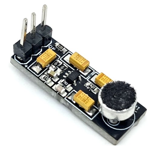
Figure 1. The assembled Microphone Amplifier with the electret microphone capsule and 3-pin header visible.
The TLV6741 is a 10 MHz op amp with low broadband noise. Its small SC70-5 package and low operating voltage make it well suited to this kind of preamplifier circuit.
The circuit uses the op amp in a transimpedance amplifier configuration, converting the microphone's current output into an output voltage. A resistive divider biases the non-inverting input at mid-supply, holding the common-mode voltage constant. This eliminates input-stage crossover distortion that would otherwise appear at the extremes of the signal swing.
Specs and Features
- Power input: 5 V DC
- Frequency response: 20 Hz to 20 kHz
- Output voltage: 1.2 V
- Key IC: Texas Instruments TLV6741 op amp (SC70-5 package, 10 MHz, low broadband noise)
- Microphone: PUI Audio condenser microphone (MK1)
- Single 3-pin header for power, ground, and audio output
- PCB dimensions: 22.54 mm x 8.26 mm
How It Works
The electret microphone MK1 generates a small AC current in response to sound pressure. Capacitor C4 couples that signal into the inverting input of the TLV6741. Resistor R1 and capacitor C4 set the input high-pass corner. Feedback resistor R3 and capacitor C3 set the gain and the upper-frequency roll-off of the amplifier, together defining the circuit's 20 Hz to 20 kHz passband.
Resistors R2 and R5, along with capacitors C6 and C1, bias both op amp inputs at mid-supply. This bias network keeps the amplifier centered between rail and ground. As a result, the output swings symmetrically around 1.2 V without clipping or crossover artifacts. On the output side, resistor R4 and capacitor C5 form an output filter and DC-blocking network before the signal reaches header CN1. Resistor R6 provides a bias path for the following stage.
Schematic and Bill of Materials
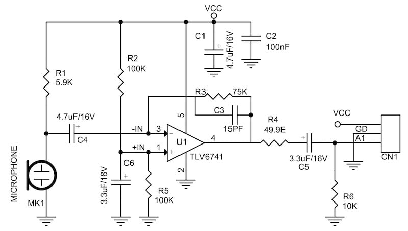
Figure 2. Schematic of the Microphone Amplifier.
The bill of materials is shown in Table 1.
Table 1. BOM for the Microphone Amplifier
| REF | DESCRIPTION | QTY | MFG | SUPPLIER | PART NO. |
| CN1 | 3 pin male header, pitch 2.54 mm | 1 | Wurth | Digikey | 732-5316-ND |
| C1, C4 | 4.7 µF / 16 V tantalum, 1206 | 2 | Kemet | Digikey |
|
| C2 | 100 nF / 50 V ceramic, 0805 | 1 | Yageo/Murata | Digikey |
|
| C3 | 15 pF / 50 V ceramic, 0805 | 1 | Yageo/Murata | Digikey |
|
| C5, C6 | 3.3 µF / 16 V tantalum, 1206 | 2 | Kemet | Digikey |
|
| MK1 | Condenser microphone | 1 | PUI Audio | Digikey | 668-1197-ND |
| R1 | 5.9 kΩ 1%, 0805 | 1 | Yageo/Murata | Digikey |
|
| R2, R5 | 100 kΩ 5%, 0805 | 2 | Yageo/Murata | Digikey |
|
| R3 | 75 kΩ 1%, 0805 | 1 | Yageo/Murata | Digikey |
|
| R4 | 49.9 Ω 1%, 0805 | 1 | Yageo/Murata | Digikey |
|
| R6 | 10 kΩ 5%, 0805 | 1 | Yageo/Murata | Digikey |
|
| U1 | TLV6741, SC70-5 | 1 | TI | Digikey | 296-48176-1-ND |
Connections
The board has one on-board microphone and one output header. MK1 is the electret microphone capsule, soldered directly to the PCB. CN1 is the 3-pin, 2.54 mm pitch header that carries power in and audio out.
CN1 — Power and Audio Header (3-pin, 2.54 mm pitch):
- Pin 1 = VCC, 5 V DC
- Pin 2 = GND
- Pin 3 = Audio Output
PCB Files
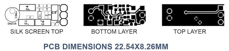
Figure 3. PCB layout for the Microphone Amplifier showing the top silkscreen, bottom layer, and top layer.
You can download the layout files for this project here:
Microphone Amplifier Gerber Files
Except where noted, all images used courtesy of Rajkumar Sharma