Facebook
 Google
 GitHub
 Linkedin
Analog Integrated Circuits
Precise Diode Circuits
14 questions By Tony R. Kuphaldt
-
Question 10 of 14
Explain how you could reverse the output polarity of this precision rectifier circuit:

Reveal answer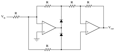
Notes:The answer to this question may seem too obvious to both asking. In reality, it’s just another excuse to analyze the full-wave rectifier circuit, complete with all currents and voltage drops!
-
Question 11 of 14
One problem with PMMC (permanent magnet moving coil) meter movements is trying to get them to register AC instead of DC. Since these meter movements are polarity-sensitive, their needles merely vibrate back and forth in a useless fashion when powered by alternating current:

The same problem haunts other measurement devices and circuits designed to work with DC, including most modern analog-to-digital conversion circuits used in digital meters. Somehow, we must be able to rectify the measured AC quantity into DC for these measurement circuits to properly function.
A seemingly obvious solution is to use a bridge rectifier made of four diodes to perform the rectification:

The problem here is the forward voltage drop of the rectifying diodes. If we are measuring large voltages, this voltage loss may be negligible. However, if we are measuring small AC voltages, the drop may be unacceptable.
Explain how a precision full-wave rectifier circuit built with an opamp may adequately address this situation.
Reveal answerA precision opamp circuit is able to rectify the AC voltage with no voltage loss whatsoever, allowing the DC meter movement (or analog-to-digital conversion circuit) to function as designed.
Notes:The purpose of this question is to provide a practical context for precision rectifier circuits, where students can envision a real application.
-
Question 12 of 14
Suppose that diode D1 in this precision rectifier circuit fails open. What effect will this have on the output voltage?

Hint: if it helps, draw a table of figures relating Vin with Vout, and base your answer on the tabulated results.
Reveal answerInstead of the output voltage remaining at exactly 0 volts for any positive input voltage, the output will be equal to the (positive) input voltage, assuming it remains unloaded as shown.
Challenge question: what mathematical function does this circuit perform, with diode D1 failed open?
Notes:Note that the given failure does not render the circuit useless, but transforms its function into something different! This is an important lesson for students to understand: that component failures may not always results in complete circuit non-function. The circuit may continue to function, just differently. And, in some cases such as this, the new function may even appear to be intentional!