Facebook
 Google
 GitHub
 Linkedin
Analog Integrated Circuits
Precise Diode Circuits
14 questions By Tony R. Kuphaldt
-
Question 13 of 14
Determine the output voltage of this circuit for the following input voltage conditions:
- V1 = 2 volts
- V3 = −1.5 volts
- V1 = 2.2 volts

Hint: if you find this circuit too complex to analyze all at once, think of a way to simplify it so that you may analyze it one “piece” at a time.
Reveal answerThe output voltage will be 2.2 volts, precisely.
Follow-up question: what function does this circuit perform? Can you think of any practical applications for it?
Notes:Another facet of this question to ponder with your students is the simplification process, especially for those students who experience difficulty analyzing the whole circuit. What simplification methods did your students think of when they approached this problem? What conclusions may be drawn about the general concept of problem simplification (as a problem-solving technique)?
-
Question 14 of 14
This circuit is referred to as a peak follower-and-hold, taking the last greatest positive input voltage and “holding” that value at the output until a greater positive input voltage comes along:
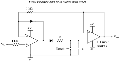
Give a brief explanation of how this circuit works, as well as the purpose and function of the “reset” switch. Also, explain why a FET input opamp is required for the last stage of amplification.
Reveal answerI’ll let you figure out how the circuit works! With regard to the necessity of FET inputs, let me say this: if the bias current of the last opamp were too great, the circuit would “lose its memory” of the last positive peak value over time.
Follow-up question: how would you suggest choosing the values of resistor R and capacitor C?
Challenge question: redraw the circuit, replacing the mechanical reset switch with a JFET for electronic reset capability.
Notes:Ask your students if they can think of any practical applications for this type of circuit. There are many!
I find it interesting that in two very respectable texts on opamp circuitry, I have found the following peak follower-and-hold circuit given as a practical example:

This circuit contains two mistakes: the first is by having the reset switch go to ground, rather than -V. This makes the reset function set the default output to 0 volts, which makes it impossible for the circuit to subsequently follow and hold any input signal below ground potential. The second mistake is not having a resistor before the reset switch. Without a resistor in place, closing the reset switch places a momentary short-circuit on the output of the first opamp. Granted, the presence of a resistor creates a passive integrator stage (RC time constant) which must be kept considerably fast in order that rapid changes in input will be followed and held, but this is not a difficult factor to engineer.