Facebook
 Google
 GitHub
 Linkedin
Network Analysis Techniques
Simultaneous Equations for Circuit Analysis
25 questions By Tony R. Kuphaldt
-
Question 4 of 25
Plot the equation y = x2 on the following graph:

On the same graph, plot the equation y = x + 2. What is the significance of the point where the two plots cross?
Reveal answer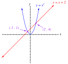
Here there are two points of intersection between the parabola (curve) and the straight line, representing two different solution sets that satisfy both equations.
Challenge question: solve this simultaneous system of equations without graphing, but by symbolically manipulating the equations!
Notes:Here, solution by graphing may be a bit easier than the symbolic solution. In principle we may determine solutions for any pair of equations by graphing, with about equal difficulty. The only real problem is precision: how closely we may interpret to points of intersection. A practical example of non-linear simultaneous function solution is load line analysis in semiconductor circuitry.
-
Question 5 of 25
Load lines are useful tools for analyzing transistor amplifier circuits, but they may be hard to understand at first. To help you understand what “load lines” are useful for and how they are determined, I will apply one to this simple two-resistor circuit:
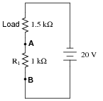
We will have to plot a load line for this simple two-resistor circuit along with the “characteristic curve” for resistor R1 in order to see the benefit of a load line. Load lines really only have meaning when superimposed with other plots. First, the characteristic curve for R1, defined as the voltage/current relationship between terminals A and B:
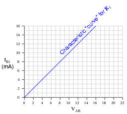
Next, I will plot the load line as defined by the 1.5 kΩ load resistor. This “load line” expresses the voltage available between the same two terminals (VAB) as a function of the load current, to account for voltage dropped across the load:
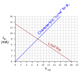
At what value of current (IR1) do the two lines intersect? Explain what is significant about this value of current.
Reveal answerIR = 8 mA is the same value of current you would calculate if you had analyzed this circuit as a simple series resistor network.
Follow-up question: you might be wondering, “what is the point of plotting a ‘characteristic curve’ and a ‘load line’ in such a simple circuit, if all we had to do to solve for current was add the two resistances and divide that total resistance value into the total voltage?” Well, to be honest, there is no point in analyzing such a simple circuit in this manner, except to illustrate how load lines work. My follow-up question to you is this: where would plotting a load line actually be helpful in analyzing circuit behavior? Can you think of any modifications to this two-resistor circuit that would require load line analysis in order to solve for current?
Notes:While this approach to circuit analysis may seem silly - using load lines to calculate the current in a two-resistor circuit - it demonstrates the principle of load lines in a context that should be obvious to students at this point in their study. Discuss with your students how the two lines are obtained (one for resistor R1 and the other plotting the voltage available to R1 based on the total source voltage and the load resistor’s value).
Also, discuss the significance of the two line intersecting. Mathematically, what does the intersection of two graphs mean? What do the coordinate values of the intersection point represent in a system of simultaneous functions? How does this principle relate to an electronic circuit?
-
Question 6 of 25
Load lines are useful tools for analyzing transistor amplifier circuits, but they may be applied to other types of circuits as well. Take for instance this diode-resistor circuit:

The diode’s characteristic curve is already plotted on the following graph. Your task is to plot the load line for the circuit on the same graph, and note where the two lines intersect:
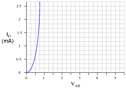
What is the practical significance of these two plots’ intersection?
Reveal answerThe two lines intersect at a current of approximately 1.72 mA:

Follow-up question: explain why the use of a load line greatly simplifies the determination of circuit current in such a diode-resistor circuit.
Challenge question: suppose the resistor value were increased from 2.5 kΩ to 10 kΩ. What difference would this make in the load line plot, and in the intersection point between the two plots?
Notes:While this approach to circuit analysis may seem silly - using load lines to calculate the current in a diode-resistor circuit - it demonstrates the principle of load lines in a context that should be obvious to students at this point in their study. Discuss with your students how the load line is obtained for this circuit, and why it is straight while the diode’s characteristic curve is not.
Also, discuss the significance of the two line intersecting. Mathematically, what does the intersection of two graphs mean? What do the coordinate values of the intersection point represent in a system of simultaneous functions? How does this principle relate to an electronic circuit?