Facebook
 Google
 GitHub
 Linkedin
Discrete Semiconductor Devices and Circuits
Thyristor Application Circuits
16 questions By Tony R. Kuphaldt
-
Question 4 of 16
The circuit shown here indicates which pushbutton switch has been actuated first. After actuating any one of the three pushbutton switches (and energizing its respective lamp), none of the other lamps can be made to energize:

Explain how this circuit works. Why can’t any of the other lamps turn on once any one of them has been energized? Also, explain how the circuit could be modified so as to provide a “reset” to turn all lamps off again.
Reveal answerOnce any one of the SCRs has been latched, the voltage available at the switches for triggering the other SCRs is substantially reduced. A normally-closed “reset” switch may be installed in series with the battery to reset all lamps back to the “off” state.
Challenge question: how could this circuit be modified to serve as a “first place” detector for runners competing on three different tracks? Draw a schematic diagram showing suitable sensors (instead of pushbutton switches) for detecting the passage of the three runners.
Notes:Discuss the operation of this circuit with your students in detail. It serves as an excellent practical example of SCR action, as well as a good review of general diode action. Ask them why an NC switch connected in series with the battery would serve to reset the SCRs.
A good question to challenge students’ understanding of this circuit is to ask them how to “expand” it to include four, five, or six lamps instead of just three.
I found this circuit design in the October 2003 edition of
Electronics World magazine. The original circuit, submitted to this periodical by M.J. Nicholas, appears on page 35 of the magazine in a slightly different form, with four lamp circuits instead of three, and using regular rectifying diodes instead of Schottky diodes as I have shown.
-
Question 5 of 16
This crowbar circuit has a problem. It used to work just fine, and then one day it blew the fuse. Upon replacing the fuse, the new fuse immediately blew:
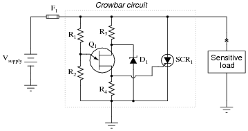
Measuring the supply voltage with a voltmeter, everything checks out well. There does not appear to be an overvoltage condition causing a legitimate “crowbar” event in the circuit. Disconnecting the load from the crowbar circuit and powering it up with a standard bench-top laboratory power supply reveals the load to be in perfect condition. Thus, both the source and the load have been eliminated as possibilities that may have blown the fuse(s).
Moving on to the crowbar circuit itself, identify some component faults that could (each, independently) account for the problem, and explain your reasoning.
Reveal answerPossible faults (not an exhaustive list)
- SCR failed shorted
- Zener diode failed shorted
- R1 failed shorted
- R2 failed open
- R4 failed open (especially if SCR is a sensitive-gate type)
- UJT Q1 failed shorted between base terminals
Notes:Discuss with your students the initial troubleshooting steps described in the question. What strategy or strategies is the technician taking to isolate the problem?
-
Question 6 of 16
What purpose does the TRIAC serve in this circuit?
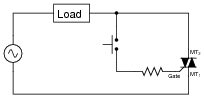
Why use a TRIAC at all? Why not just use the switch to directly handle load current as in this next circuit?
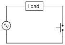
Reveal answerThe difference between these two circuits is a matter of switch currents. If you understand how a TRIAC works, the answer to this question should not be too difficult to figure out on your own.
Notes:A benefit of this circuit that is easy to miss is the TRIAC’s ability to provide zero crossing turn-off. Discuss why this might be important when controlling power to inductive loads.