 Facebook
 Google
 GitHub
 Linkedin
Teardown Tuesday: Epson XP-330 Printer
In this teardown, we investigate the PCBs, LCD, motors, and ribbon cables found inside the wireless all-in-one Epson XP-330 Printer.
This week, we rip into an inkjet printer with LCD screen and wireless connectivity.
At A Glance
The Epson XP-330 Printer is advertised as being a wireless color photo printer with a scanner and copier. Its features include:
- 1.44" color LCD.
- Complete wireless solution—easy iPad, iPhone, Android tablet and smartphone printing; includes Wi-Fi Direct for network-free printing.
- Truly touchable photos and documents—instant-dry ink for smudge-, fade-, and water-resistant prints.

Epson XP-330. Image courtesy of Amazon.
Lots of Plastic
I must praise the mechanical engineers/designers for creating a very solid plastic enclosure. During this teardown, I discovered that, relatively speaking, very few screws are used in the design—I counted 35 screws during the disassembly process.
What amazes me most, however, about this design is how cleanly and solidly the plastic pieces fit together—the fit and finish is superb!
Also, many ribbon cables (seven) are used to achieve connectivity between the various PCBs. I'm sure that using ribbon cables was less expensive than using regular cables. Also, using ribbon cables makes for a cleaner overall design.
Few wires/cables are used in this design, and two of them are used for powering the two DC motors. I presume that wires are used for the motors because of their higher current carrying requirements. You can see a view of the printer with much of the plastic removed further down.
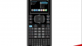
Front Control Panel PCB
The first PCB examined was the one located inside the front control panel. This PCB is a two-layer board. It's a high-quality and a professional looking board with the following components:
- Color LCD made by giantplus.
- Three 8-bit shift registers:

Front control panel PCB.
AC/DC Power Supply
This 3rd party OTS (off the shelf) power supply is made by Bestec (p/n EP-AG210SDE). According to its specifications, it's a universal AC input (meaning 90 to 264 VAC) with a DC output voltage of 42V.
Take note of the ferrite bead on the output cable. This bead provides EMI filtering/protection.

AC/DC power supply (42VDC).
SD Memory Card Reader PCB
The card reader allows the printer to acquire data (pictures) directly from an SD memory card:

SD memory card reader PCB.
Components and features include:
- SD card reader IC (p/n: RTS5 186) made by Realtek. No datasheet could be found.
- 12MHz TXC Crystal. Note the black dot on this crystal. This dot—signifying that this device works as expected—was most likely applied during some sort of verification or qualification testing.
- Note that the PCB's copper is exposed in one corner. This exposure allows a metal screw, which anchors the PCB in place, to electrically ground the PCB to the printer's metal structure/chassis.
- Similar to the power supply cable above, the ribbon cable associated with this PCB uses a ferrite bead for EMI protection/filtering.
2.4GHz Wireless Module PCB
Based on the information provided by the label attached to the wireless module, Epson designs and manufactures their own Wi-Fi modules.

Wireless module.
It makes since that Epson has taken this approach, as opposed to using 3rd party devices, since they are one of the world's largest manufacturers of computer printers. This allows Epson to have complete control over the wireless connectivity of their printers. Below are some noticeable items about this module:
- Based on visual inspection, this board appears to be of high quality in terms of both design and manufacturing.
- The wires are protected (from the printer's internal sheet metal edges) with what looks to be an ironed on, or otherwise heat activated, fabric. The fabric is far superior than the typical wire-protecting plastic widgets that I've seen used in other designs. This fabric piece does not, in the slightest, slide around on the cable—it stays exactly where it's supposed to. Nice work!
- The wireless module itself is covered with a metal shielding box.
- Note: the metal shielding box has been soldered to the PCB along all four sides, except of course where PCB traces exit. This is the ideal approach as it closely mimics a faraday cage, meaning the EMI shielding effectiveness has been maximized as much as possible.
Position Sensors
The printer has two position sensors (AKA optoelectronic devices).

Two position sensors (AKA optoelectronic devices).
One position sensor is used to track the position of the paper.

Position sensor used for tracking paper's position.
The second sensor is used to track the location of the ink tray.

Position sensor used for tracking the location of the ink tray.
Both PCBs are well designed and manufactured.
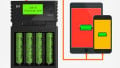
DC Motors
This printer uses two DC motors. One motor controls the rollers that move the paper. The second motor controls the movement of the ink tray. According to the motors' specifications, these motors are carbon-brush motors and are rated to operate up to 42VDC.

42V DC motors
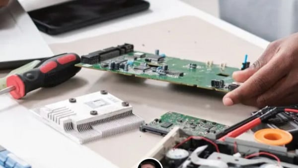
Primary PCB
The primary PCB is the final board examined. The vast majority of board-to-board connections are achieved using ribbon cables. The primary board has seven ribbon cable connectors of various sizes. Other features and components on this board include:
- Multiple Epson ICs, including the printer driver. No datasheets could be found for these ICs.
- High capacitance value electrolytic capacitors, including 100µF and 220µF.
- Two bipolar transistors. These devices are advertised for controlling motors.
- SK Hynix DRAM. No datasheet could be found for this device.
- The PCB is a multi-layer board. I would guess it's a four-layer board.
- This board, like all the other boards in this design, is of high quality.

Primary PCB.
Summary
Surprisingly, I'm impressed with how well designed, thought out, and manufactured this printer is. Plastic enclosure pieces were used as much as possible, which helps to keep the low price of this printer at about $50
The manner in which the ferrite beads are attached to the ribbon cables suggest that these EMI countermeasures were decided upon near the beginning of the design, as opposed to using them as a band-aid to fix an EMI problem. All in all, I consider this a great printer design!
Next Teardown: Induction Cooktop


do you have a schematics for teh main board…I have to know how connect the L2 inductor, because it is about 4 pins on the board…An acident…and I have to put an inductor again…