 Facebook
 Google
 GitHub
 Linkedin
A Brief Sweep of the Current Measurement Landscape
There are many ways to do the job, each with its own set of advantages, disadvantages, and best use cases.
There are a number of reasons to measure current.
The first and most obvious one is to measure the power required by a design. It might be important to know how much current a subsystem is using, so circuitry can take dynamic action in response. In the design phase, knowing how much current is used in any node may make it possible to shed a heavy component for a smaller, cheaper, and lighter substitute.
Depending on the reason for current measurement, engineers are also faced with manifold methods for measuring current. So, what would it take to "redefine the current measurement landscape?"
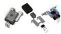
Yesterday, resistor specialist Reidon claimed to offer a game-changer in the current measurement market with an isolated high-power shunt module, the SSA Smart Shunt, which they claim is an alternative to Hall effect current sensors.

SSA Smart Shunt. Image used courtesy of Reidon
While Reidon doesn't go into detail on how, exactly, the smart shunts rival Hall effect sensors, this topic gives us an opportunity to review some common methods of current measurement. While this review is by no means exhaustive of all the methods available, it will give you an at-a-glance idea of the ways engineers measure current.
Hall Effect Sensors
The Hall effect describes how electrons moving through a conductor are affected by the presence of a magnetic field.

The Hall effect with no magnetic field (top) vs. with magnetic field (bottom). Image (modified) used courtesy of Vishay
The image on the top illustrates how in the absence of a magnetic field, no voltage difference is noted between the sides of the conductor. The image on the bottom shows that in the presence of a magnetic field, electrons migrate, and there is a measurable voltage differential (VH) between the top and bottom of the strip. In Robert Keim's technical article on the Hall effect, he describes the physics behind this phenomenon.
Voltage VH, though generally quite small, is directly proportional to the current passing through the conductor. As long as the magnetic field is held steady, VH is a reliable surrogate measure of that current.
As an example, Broadcom’s ACHS-719x family are Hall-effect based current sensors for AC or DC current sensing in industrial, commercial, and communications systems. The devices are for ±10A to ±50A ranges and provide electrical isolation.
Current Sensors Based on Rogowski Coils
A Rogowski coil works like an AC transformer. In the image below, changing currents passing through the conductor induce voltages in the Rogowski coil.

Diagram of Rogowski coil current sensors. Image used courtesy of Hioki USA
Those voltages are proportional to the rate of change of the current through the conductor. Integration yields a voltage that is proportional to the original AC current passing through the conductor.
Accuenergy's Flexible Rogowski Coil operates over a frequency range of 20 Hz to 5 kHZ and can handle currents ranging from 5 A to 50,000 A.
CT Current Sensors
Current transformer (CT) sensors work on a similar principle to Rogowski coils.

CT current sensors. Image used courtesy of Hioki USA
In a manner analogous to a transformer, the AC current that is measured as it passes through the conductor induces a magnetic flux in the magnetic core. The changing flux generates a voltage in the secondary coil. That voltage, measured across the shunt resistor, is directly proportional to the conductor’s current.
An illustration of this comes from Magnelab with its UCT-1250, a solid-core current transformer with a large 1.25-inch opening that can work with up to 400 A.
Shunt Resistors
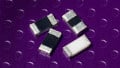
Perhaps the simplest method for current measurement is to employ shunt resistors.

Shunt resistors for current measurement. Image from "Ammeter Design" worksheet
A precision “shunt” resistor is placed in series with the current to be measured. The voltage across the resistor is measured, and of course, the resistance is known. The current flowing across the resistor can be determined directly through Ohm’s Law; I = E/R.
Vishay offers an extremely wide range of such current sensing resistors.
Pros and Cons of Current Measurement Methods
Of course, the two transformer-like methods—the Rogowski coil and the CT current sensors—can only be used for AC measurements.
Hall effect sensors are usually built on p-type semiconductor material and not copper. They are unaffected by ambient conditions, including vibration, dust, and humidity. They also operate over a wide temperature range and can measure large levels of current. On the other hand, their accuracy is affected by unanticipated or stray magnetic fields.
Rogowski coils are not closed-loop but are rather open-ended and flexible. The coil can be placed over a live wire without disturbing it. However, placement can be critical. Additionally, designers must supply operating voltage to the required integrator circuitry.
The obvious disadvantage of the shunt resistor is the power loss across it, since P = I2R. Additionally, there is no inherent “transformer” to provide electrical isolation, so interfacing can be problematic.
CT sensors are often employed for tracking the energy consumption of an entire building, Their great advantage is that they can achieve this function without any direct high voltage wiring.
As with any design method, your current measurement technique largely depends on application requirements.
Which method of current measurement do you use most frequently? Why? Share your experiences in the comments below.


In my practice, I follow the rule: for low currents (mA) - methods for direct measurement, for measurement of high currents - indirect methods.