Facebook
 Google
 GitHub
 Linkedin
An Integrated High-Current Power Module: 0.5 to 2 Volt at 35 Amps from Texas Instruments
Texas Instruments has released a fixed-frequency step-down power module that delivers up to 35 Amps at output voltages ranging from 0.5 to 2 V.
Texas Instruments has released a fixed-frequency step-down power module that delivers up to 35 Amps at output voltages ranging from 0.5 to 2 V.
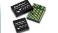
Texas Instruments' TPSM846C24 is a fixed-frequency step-down DC/DC converter that incorporates the controller, the power MOSFETs, the inductor, and their associated components into a 59-pin QFM (quad flat module) package. As you can see, this is not the sort of footprint that you are likely to find in your CAD library.
_pads.jpg)
Not exactly a standard package...
The device is highly integrated, there’s no doubt, but it does require several external passive components that are used to set the operating parameters. Although the figure below may look a bit overwhelming at first glance, in reality the task of selecting these components is not too difficult...given all the helpful guidance that TI has provided within the datasheet. Thanks, TI!
_typical_application.jpg)
The TPSM846C24 and its external components. Diagram taken from the datasheet (PDF).
External Components
Minimum Capacitance Requirements
According to the section entitled Minimum Capacitance Requirements (Section 7.3.1 on page 12), in order for this device to operate properly, the following minimum capacitance requirements must be met:
- Input capacitance: four 22 µF (or two 47 µF) ceramic capacitors plus a 330 µF bulk capacitor (C1–C5 in the figure above).
- Output capacitance: four 47 µF (or two 100 µF) ceramic capacitors plus two 470 µF, low-ESR polymer capacitors; the combined ESR of the polymer capacitors must be no greater than 5 mΩ (C10–C15).
- Analog power path (VINBP) bypass network: a 1 µF ceramic capacitor and a 10 nF ceramic capacitor must be connected across pins 50 and 51 (C7 and C8).
- Two internal LDOs: the 6.5 V rail requires a 4.7 µF ceramic capacitor (C6) across pins 48 and 49, and the 3.3 V rail calls for a 2.2 µF ceramic capacitor (C9) across pins 47 and 51.
Compensation Network
This module requires an external resistor-capacitor (RCOMP, CCOMP) compensation network placed across pin 6 (DIFFO) and pin 7 (FB); the value of these components is a function of the total amount of output capacitance and the IC's operating frequency. And while the datasheet recommends values for these two components and suggests that only low-ESR and polymer-type capacitors should be used, TI advises us that "final values should be determined by testing system stability using standard power supply evaluation techniques."
_compensation_network.jpg)
Recommended values for CCOMP and RCOMP, from the datasheet (PDF).
Setting the Output Voltage
As mentioned previously, this power module is capable of providing an output voltage (VOUT) ranging from 0.5 to 2.0 V. A single resistor, namely RSET, is all that's required for setting this voltage; this resistor, as depicted in the figure below, is placed between pins 7 and 10, and its value can be calculated using the equation shown in the figure.
_Rset.jpg)
The RSET resistor. Diagram and table taken from the datasheet (PDF).
Differential Remote Sense
Because of the large output current capabilities of this power module, accounting for the associated IR drop is important when considering load regulation. “IR drop” refers to the voltage drop across resistance that is present between the module and the load. You might be wondering why designers would insert a resistor in this high-current path. Well, normally they wouldn’t, but we still have unintentional resistance presented by the module’s contacts and the PCB traces. This resistance is low, but low resistance can still cause non-trivial voltage losses when you’re dealing with high currents.
This IC offers a differential remote-sense amplifier that allows you to sense the voltage directly at the load and thus bypass the IR drop. See Section 7.3.5 (Differential Remote Sense) in the datasheet for more information.
High Current Capabilities
If you like this part but find that 35 A is not enough current for your application, don’t look elsewhere just yet, because this power module can be connected in parallel with a second device for a total output current rating of 70 A.
While we’re on the subject of pushing output currents toward the max, remember that whenever you’re dealing with high currents, it’s a good idea to devote some time to thermal considerations (i.e., moving heat away from the components and into the surrounding environment). And although this device can operate in ambient temperatures up to 105°C, its capabilities are not completely immune to high-temperature environments, as shown by the derating plots below.
_SOA.jpg)
Derating plots, from the datasheet.
Layout Recommendations
The TPSM846C24—along with numerous other high-performance, highly integrated ICs and modules—cannot provide optimal performance if you don’t give it an optimal layout. Fortunately, in addition to two pages on PCB layout guidelines (see pages 24–25), including top-side and bottom-side PCB layout recommendations (see the image below), TI has provided four pages related to the package itself, including a detailed package outline, solder mask and solder paste details, and a land-pattern example. These are all especially handy since this package appears to be quite unique.
_layout_top-bottom.jpg)
The datasheet provides an example of a top-side and bottom-side PCB layout.
Have you had a chance to use this new power module from TI? Or have you attempted to compare this device to µModule components from Linear Tech? If so, leave a comment and tell us what you think.
Related Content