Facebook
 Google
 GitHub
 Linkedin
Working with Fluctuating Input Supplies: A New Tiny DC/DC Buck Regulator from Linear Technology
A new, smaller, and more versatile DC/DC step-down voltage regulator that's designed for noisier applications such as avionics, factory automation, and industrial robotics.
A new, smaller, and more versatile DC/DC step-down voltage regulator that's designed for noisier applications such as avionics, factory automation, and industrial robotics.
Linear Technology, now part of Analog Devices, recently announced their new tiny, powerful, and versatile LTM8063, which is a 2A µModule buck regulator that accepts input voltages as high as 40V. Using Linear Tech's Silent Switcher architecture to minimize EMI emissions, the LTM8063 is able to pass the CISPR 22 class B EMC standards. And its wide input voltage range (3.2V to 40V) allows the regulator to operate well with unregulated or fluctuating supply voltages. Seems impressive.
When I say tiny, I'm not only referring to the IC package itself, which is indeed small, but I'm also taking into account the tiny overall solution, which includes the required four external passive components: two caps and two resistors. As discussed in the LTM8063 news release, the IC package itself, a 28-pin (6.25 × 4 × 2.22 mm) BGA IC, is 75% smaller than existing equivalent voltage regulators, and when using two 0805 capacitors and two 0603 resistors, the total solution is a mere 70mm2. Figure 2 below shows a suggested layout, though in this case the two capacitors are different sizes.

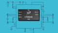
Figure 1. This 2A µModule buck regulator comes in a tiny 28-pin BGA package. Image taken from the datasheet (PDF).

Figure 2. A suggested PCB layout, from the datasheet (PDF).
Flexible and Versatile
What makes this DC/DC voltage regulator so flexible is the ease with which you can change its operating frequency and VOUT setting. Being able to easily, quickly, and inexpensively change the regulator's switching frequency is huge when troubleshooting EMC issues, especially when you're in a rented EMI lab paying by the hour or by the day, or, even worse, when you're in the critical path of either a new product introduction or a first-to-market mandate. Ugh!
The wide VOUT range (from 0.8V to 15V) provides serious versatility: a designer can use this one IC in multiple locations on a PCB for generating a variety of voltage rails, such as 1.8V, 2.5V, and 3.3V. When I designed solid-state drives, these three rails were often used. And of course you can also reuse a proven design in future projects; the VOUT range covers the supply voltages required by most of the low-voltage systems that so many engineers work on these days.
This buck regulator uses a constant-frequency PWM architecture whose switching frequency can be set using a single resistor that connects between the RT pin and ground; the frequency range is 200kHz to 2.2MHz. And because Linear Tech has provided recommended resistor values as well as guidance on the operating frequency trade-offs, choosing a suitable switching frequency should be quite straightforward. The table below lists the recommended resistor values.

Figure 3. Recommended resistor values according to switching frequency. Table taken from the datasheet (PDF).
With regard to the trade-offs involved in the selection of an operating frequency, Linear Tech cautions that choosing a resistor value arbitrarily may result in a frequency that is too high, and this may reduce the IC's efficiency, increase the heat generated by the regulator, or even damage the device itself. Similarly, a frequency that is too low may result in an output voltage that has too much ripple. For more information on this topic, read the section entitled Operating Frequency Trade-Offs in the datasheet, or simply call or e-mail Linear Tech/Analog Devices with additional questions. I'm sure they'd be happy to address all your questions...with the hope of getting this new IC incorporated into your next design.
Negative Output
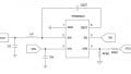
As described in the datasheet, this buck regulator is capable of generating a negative output. You accomplish this by connecting its VOUT node to the system ground and its ground node to the negative rail—see the figure below.

Figure 4. Using the LTM8063 to generate a negative output voltage. Diagram taken from the datasheet (PDF).
However, in this configuration, the IC is not behaving as a true buck regulator, and the maximum output current will be a function of the IC's input voltage; for more information review the Negative Output section in the datasheet.
Keep in mind, though, that even when generating a positive output, the input voltage needs to be taken into consideration, because higher VIN leads to significantly lower efficiency. Ambient temperature is another important factor: regardless of whether the output voltage is positive or negative, maximum load current is limited under high-temperature conditions (for details refer to the derating plots starting on page 7 of the datasheet).
A Demo Board Is Available
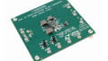
If you're not sure that you're ready to try this IC in a new design, or if you'd like to test it in your lab without taking the time to design a new PCB, then you might consider using Linear Tech's LTM8063 demo board, called the DC2494A (see image below). This board is designed for a VOUT of 5V and accepts input voltages from 6.5V to 40V.

Figure 5. The LTM8063 demo board (i.e., the DC2494A).
Have you had a chance to use this new µModule buck regulator from Linear Technology? If so, leave a comment and tell us about your experiences.
Related Content