 Facebook
 Google
 GitHub
 Linkedin
Teardown Tuesday: IR Thermometer
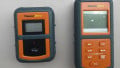
Lets take a look at the insides of an infrared thermometer.
In this Teardown Tuesday, we open up a handheld infrared thermometer and see what's inside.
Infrared (IR) thermometers are a form of contactless thermometers that determine temperature from the amount of thermal radiation emitted from an object. This device works by focusing thermal radiation onto a sensor. This type of thermometer can be a valuable tool for makers, hobbyists, and engineers.
In this Teardown Tuesday, we are going to take a look at the insides of one of these infrared thermometers.

The IR thermometer
Opening It Up

Opening up the IR thermometer
Opening up this thermometer was a breeze! Using a small flat head screw driver, the blue plastic enclosure pieces were separated from the grey plastic enclosure pieces. Once they were removed, the blue enclosure halves simply pulled apart. Five Phillips-head screws held the circuit board in place.
Circuit Board

The top of the circuit board
The circuit board is pretty typical. It is a two-layer board with green solder mask and white silkscreen on both sides. The board is 0.062” thick with an ENIG finish. The PCB is comprised entirely of surface-mount components and many of them appear to be hand-placed.

The bottom of the circuit board
Processor

The processor encased in epoxy
The brains of the thermometer is a microprocessor that is die-mounted to the circuit board. A dome of black epoxy is used to keep it in place. It is most likely a custom IC designed especially for this application.
Attached to this microcontroller is a 24C04 EEPROM that most likely saves calibration constants and settings. The EEPROM is in an SOIC-8 package.

The EEPROM
Power Supply
This IR thermometer is powered by a single 9V battery—it was even included! The battery is attached with a rigid 9-volt battery strap that is "T style”. The power wires are passed through a hole as a form of stress relief.

The wires’ stress relief
The voltage is then regulated by a 5V regulator, U3. There is a bypass capacitor on the input, C13. On the output of the voltage regulator is a 10uF 25V through-hole electrolytic capacitor on surface-mount pads, C14.

The power supply
The Sensor Assembly

The sensor assembly
In order to obtain the temperature, an IR temperature sensor is used. The sensor is located in an aluminum housing with a Fresnel lens placed in front of it. The sensor is mounted to a small circular circuit board. The sensor is a 4-pin through-hole device in a metal housing. Three wires connect the circular circuit board to the primary circuit board.

The IR sensor
Display

The LCD display
A segmented LCD display is used to show the temperature and various other information. The display is connected to the circuit board using an elastomeric connector to connect the 24 circuits.
The display uses a piece of transparent plastic to diffuse the backlight. There were also two thin white plastic sheets that aided in the diffusion, not pictured.

The components of the display
The display is backlit using two SMD LEDs, D1 and D3, that are soldered to the board at a 90 degree angle. This provides a blue backlight to the display.

The blue LED is used for the backlight
Laser

The laser assembly
To aid in aiming the thermometer, a red laser is used. The laser is activated when the measurement trigger is pulled. There is also a UI button to disable the laser.
The laser is mounted in a brass housing with a small driver attached, covered in black heat shrink. The image below shows the brass laser module that was glued in place and the laser driver. These were damaged during removal (note the bent and broken pins).

The laser driver and laser module
Conclusion
These IR thermometers are relatively low-cost devices that are pretty simple. At one time, these were very expensive, but they have gotten cheaper and cheaper. They are now made in huge quantities and sold everywhere from Lowes to Walmart. Thanks for taking a look at this teardown! Stop by next week for another one!
Next Teardown: Hi-Fi Audio Amplifier with Bluetooth


Got one from ebay after looking at the ripapart.
Built well.
Works great.
thanks for the ripdown report. 😊
the plastic even feels nice.