Facebook
 Google
 GitHub
 Linkedin
Teardown Tuesday: ThermoPro’s TP07 Wireless Digital Meat Thermometer
In this teardown, we tear open ThermoPro's TP07 wireless digital meat thermometer.
In this Teardown Tuesday, we tear open ThermoPro's TP07 wireless digital meat thermometer to take a look at the sensors, LCD, and more.
First Impressions
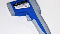
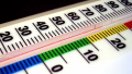
When I first picked up the ThermoPro TP07 Wireless Digital Meat Thermometer my first impression was, "Wow, this is extremely light." I was expecting it to weigh as much as a typical DMM, but I was pleasantly surprised. Also, my initial reaction to the orange plastic case was that it felt a little cheap.
However, given the following features (along with a price tag of under $40), I can easily overlook the feel of the plastic. The rubber sleeve case—besides adding a nice touch—helps prevent the device from sliding off your counter/oven/BBQ/smoker, which is handy.

ThermoPro's TP07 wireless digital meat thermometer
Some of the ThermoPro's TP07 features include:
- Temperature range: 32°F to 572°F (0°C to 300°C), ±1.5°F/0.8°C accuracy
- Smart LCD backlit screen: shows three different colors in reaction to different temperatures it receives
- Programmed with preset temperatures for different types of meat
- Programmed with preset doneness levels for different types of meat
- Remote range: up to 300 feet
- Count-down and count-up timer
- Alarm
- Easy setup: no transmitter-to-receiver synchronization required
Opening the Transmitter Module
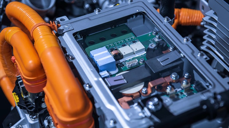
After removing four small screws, I was able to look inside the transmitter module.
Given all the cool features offered by this device, I was expecting a lot more in terms of electronics. The design appears to be a quite basic and simple.
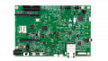
![]()
The internal components of the transmitter module.
The two things that I immediately noticed after cracking open the case were the long green antenna (which means the transmitting frequency is sub-gigahertz) and the black blob of epoxy. Manufacturers typically use black epoxy when they want to hide some of their proprietary information—the microcontroller in this case.
Removing eight more screws allows the two PCBs to be released from the orange plastic case. The larger PCB appears to be made as inexpensively as possible. It's a two-layer board (i.e., no internal layers) and it doesn't have any large copper areas. This fact is very evident when holding the PCB up to a light bulb which allows us to see traces on both sides of the PCB.
![]()
PCB held up to a light bulb. Note the lack of large copper areas.
The small PCB—which includes the transmitting IC—is also a two-layer board, but it does include a rather larger copper area which is beneath nearly all of the components. This copper area—a ground plane—is necessary for maximizing the antenna's transmitting range. Both PCBs have a thickness of 0.040" (40 mils), which is an industry standard PCB thickness.
![]()
Two PCBs and LCD screen.
PCB Components:
- LCD screen: This screen has an HSK marking along with an HIT34444-0 part number, but no datasheet could be located.
- Notice that this LCD screen has no wires or metal leads attached to it. Rather, it uses a pink foam-like material for making electrical connections. This foam-like material is called an elastomeric connector, also known as a Zebra connector.
- Transmitter IC: This 300-400MHz RF transmitter carries part number CYF115. The IC is advertised as being an easy-to-use single chip ASK transmitter intended for remote wireless applications in the 300 to 450MHz frequency band. Also, it's referred to as a true “data-in, antenna-out” monolithic device.
- Transmitter IC crystal: This is a 13.560MHz crystal. This is the exact frequency referenced in the transmitter IC datasheet.
- Microcontroller crystal: The microcontroller uses the very common crystal frequency of 32.768KHz.
- EEPROM: This two-wire serial interface memory device is made by the company Lize and has part number L24C02B4S1. Honestly, I'm surprised that an EEPROM is used at all. I would think that the microcontroller has enough memory. But, perhaps, it has no Flash memory (i.e., non-volatile memory)—which conceivably reduces the cost of the microcontroller—thus the need for an EEPROM.
- Transistor: This PNP transistor has the package IC marking of 2T1.
- Microcontroller reset IC: This Maxim Integrated supervisory circuit is used to monitor (and reset, when necessary) the microcontroller's power supply. This device has a marking of AFAA.
Opening the Receiver Module
Similar to the transmitter module, the receiving module also uses four screws for holding it together. And also like the transmitter box, this receiver design looks very straightforward.

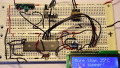
Looking inside the receiver module.

Major pieces removed and disassembled.
The main PCB components include:
- Receiver IC: Although this device is absent of any IC markings, I'm assuming that it's part CY580 from CY—the same manufacturer as the transmitting IC, which is a 300-450MHz Receiver IC.
- Receiver IC crystal: This crystal is marked as a 6.7458MHz device.
- LCD: Similar to the transmitter design, this design uses an elastomeric connector for attaching the LCD screen to the PCB. And, also like the transmitter LCD screen, no datasheet could be found for this LCD screen.
- EEPROM: The EEPROM has part marking T24C02A.
- Three-color LED: This is used for backlighting the LCD screen. This is a really cool concept! When the LED illuminates, the clear plastic screen diffuses the LED's light which illuminates the LCD screen. The LCD screen, itself, has no internal lighting capabilities.
- Exposed copper traces: These are necessary for allowing the silicone rubber keypad buttons to make electrical shorts between the various copper traces/signals. This electrical shorting allows the microcontroller to know which button has been depressed.
- Audio alarm: This has no markings at all.
- NPN transistors: These are marked as J6.

Primary PCB components called out.
Complies with FCC Regulations
As can be seen on the label, shown below, the appropriate FCC compliance sticker is attached to the device, meaning that this device conforms to the FCC rules regarding EMI and EMC.

FCC compliance label
Summary
ThermoPro's TP07 Wireless Digital Meat Thermometer is very popular according to Amazon's 4.5 review stars—with 1900+ customer reviews! And I, too, really like this device given its many functions, wireless capabilities, and simple designs.
Finally, as long as one could find replacement parts, both the transmitter and receiver modules could easily be serviced/repaired if need be. Well done, designers, on making this device very easy to service!
Next Teardown: Epson XP-330 Printer
Related Content