 Facebook
 Google
 GitHub
 Linkedin
How to Stream Sensor Data from Bosch’s XDK110 Evaluation Board to the MQTT Messaging Service
In this article, we will take a look at the XDK110 rapid prototyping kit, characterize its hardware, explore its software environment, and demonstrate connecting the device to the MQTT messaging service.
This project uses the XDK110 wireless sensor development kit to stream sensor data, in this case to the MQTT messaging service.
In this article, we will take a look at the XDK110 wireless sensor device, characterize its hardware, explore its software environment, and demonstrate connecting the node to the MQTT messaging service.
The XDK110
The Bosch XDK110 is a multifunction device that includes multiple MEMS (microelectromechanical systems) sensors:
- Accelerometer
- Acoustic sensor
- Gyroscope
- Magnetometer
- Light sensor
- Humidity/pressure/temperature sensor
- Inertial measurement unit
It also includes a microSD card slot, two momentary switches, three programmable LEDs, and enables wireless network and Bluetooth Low Energy (BLE) connectivity. Programming and configuration of the device are done through the XDK-Workbench IDE.
The XDK110 allows users to program the device to communicate events or stream raw sensor data, allowing sensor functionality in new devices or adding it to old devices.
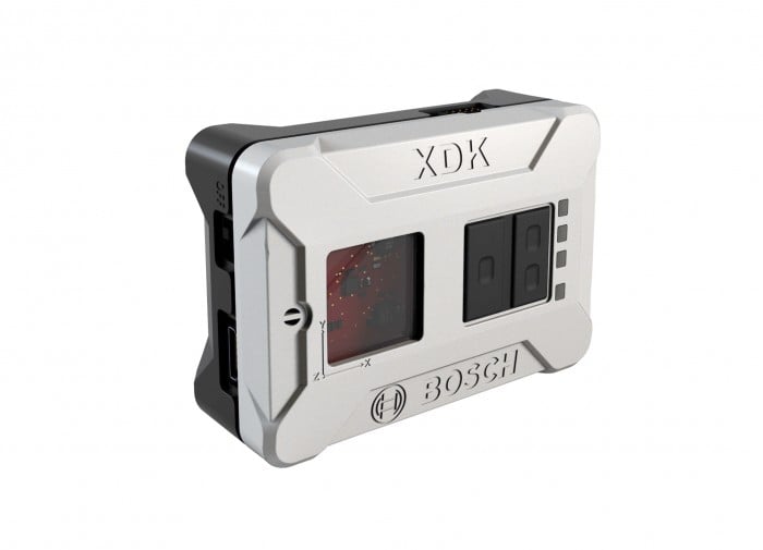
The Bosch XDK110
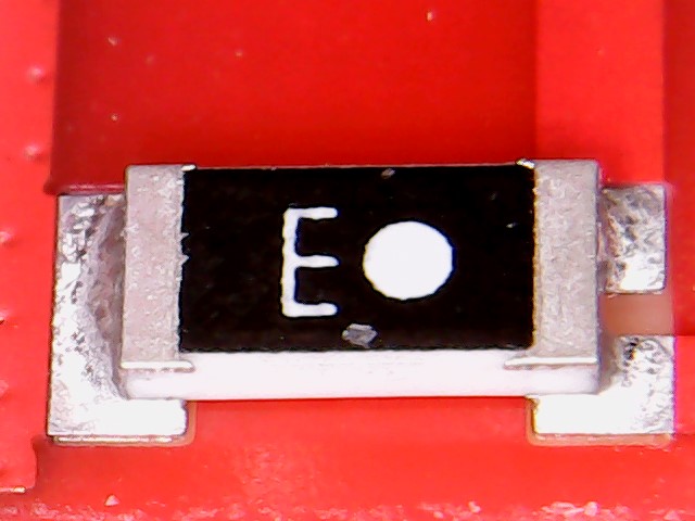
The Bosch XDK110 PCB (front and back), with and without part numbering.
Shown above is the single circuit board that is present inside the Bosch XDK110.
The gif above identifies the parts on the board as follows:
- Power switch
- MicroUSB
- Texas Instrument CC3100 SimpleLink™ Wi-Fi® network processor, Internet-of-Things solution for MCU applications
- 0.05” 2×5 JTAG programming header
- RFI shield covering Bluetooth chip and surrounding passive components.
- SD card slot
- ESD or level-shifting ICs for expansion connector
- Expansion connector
- IC marked APH
- IC marked “157 1433”
- Microphone
- IC marked “036 DA”
- IC marked “1A”
- Ambient light sensor
- IC marked “007 A533 030”
- IC marked “021 TS”
- IC marked “ZVK 58J”
- IC marked “WK”
- EFM32 Gecko 32-bit microcontroller
- IC marked "CKP TI 571"
The sensor ICs are so small that there is not room for full identifying information. The top-side markings might be IC identifiers or perhaps batch or date codes. If you work with Bosch Sensortec ICs and run across a sensor with similar top-side markings as those listed above, please comment below and I will update the list.
The PCB is constructed exclusively of surface-mount components and routes almost all signal traces on internal layers of the board. The top and bottom layer copper-pours are stitched together with an array of through-vias that are not visible in the photograph. Via-fencing surrounds two ground clearance areas that extend through all layers of the board. On the top of the board are two chip antennas that connect to the BLE and WiFi ICs.
The designers made the choice to forgo silkscreen part-orientation and markings, and instead use solder-resist and text printed in copper for the few markings that do appear on the board.
This lack of markings is a dangerous choice for early design stages and should be reserved for the last stages of manufacture, as it is far too easy for a board manufacturer to incorrectly orient an IC or a test engineer to tap the wrong test pad.
The main processor used in this design is an EFM32 microcontroller from Silicon Labs. The metallic outline around this microcontroller and its support components may be a solder connection for an RFI shield that turned out to be unnecessary.
The only part of the circuit board I cannot see is whatever is enclosed in the RFI shield (labeled as #5 in the image above). The only clue to what lies beneath is a trace that emerges from beneath the metal shield and connects to one of the chip antennas.
This approximately 0805-sized component is a chip antenna simlar to the one described in this datasheet
Shown but not highlighted in the above image (near the EFM32) are four LEDs and two pushbutton switches. Not shown is the battery that powers the device.
Watch my video below to see some of the ways I put the XDK110 to work:
Programming the Device for Use
XDK Workbench
A new version of the Bosch XDK Workbench was recently released. Before attempting to program the XDK110 using the software examples provided by the websites shown below, confirm that the code will work with your version of XDK Workbench, as some of the examples are not maintained by Bosch XDK group.
The software examples provided inside the XDK Workbench are updated by Bosch and should work.
Software Integrations for the XDK110
The XDK Workbench is an Eclipse-based IDE (Integrated Development Environment). Several examples are provided to demonstrate functionality and provide a jumping-off point for software developers. Additional software for the device can be found at the following developers’ websites.
- Bosch Software Innovations
- Zatar
- Relayr
- Evothings
- Bosch Engineering
- Bosch Sensortec
- BellaDati
- LEM IoT
- Appropos
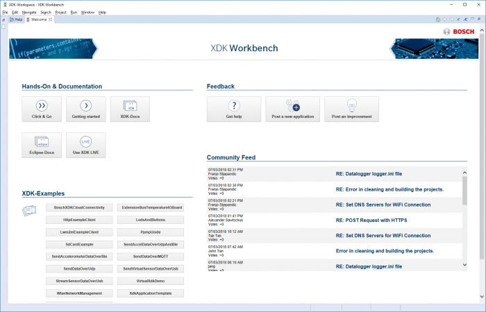
If you are familiar with Eclipse, the XDK Workbench should be relatively easy to use. A set of examples in the welcome screen under the heading “XDK-Examples” provides the code necessary to allow most developers to get started immediately. Documentation in the “XDK-Docs” tab provides information about the various sensors available, how to configure them for use, and how to access their data.
Programming Examples
XDK Live
Of particular interest inside the XDK Workbench is software called “XDK Live”. This is an event-based source-code creation tool that should allow non-programmers to create the source code necessary to run the XDK110. The software is still in the early stages of the software development cycle but, given time, XDK Live may supplant traditional programming in many use-cases.
The XDK Live language is an abstracted, event-based language. It executes code when certain conditions are met—for example, when a certain period of time has elapsed, when a button is pressed, or when a sensor value exceeds a predefined value.
You can very quickly write code that tells you if a motor is vibrating too much, a CNC machine is making too much noise, or a forklift is on too steep an incline.
The following XDK Live code creates a Bluetooth Low Energy device that transmits the recorded temperature once every five seconds. It does this by interpreting the XDK Live code and using it to create C++ source code that is compiled and uploaded to the device.
// The following code belongs to the main package
package main;
// The XDK110 is the device used
import platforms.xdk110;

// Setup a BLE instance named myPhone
setup myPhone : BLE {
// Name of the sensor seen by other BLE devices
     deviceName = "BoschXDK";
     // Advertising interval in milliseconds.
     advertisingInterval = 2000;
     // The last four digits of the device UUID are assigned to the 32-bit characteristic
     // for temperature(measured in thousandths of a degree Celsius).
     var myTemperature = int32_characteristic(UUID=0xAACC);
}

// Do this every 5 seconds
every 5 seconds {
     // Write the current temperature value to myTemperature variable
     myPhone.myTemperature.write(environment.temperature.read());
}
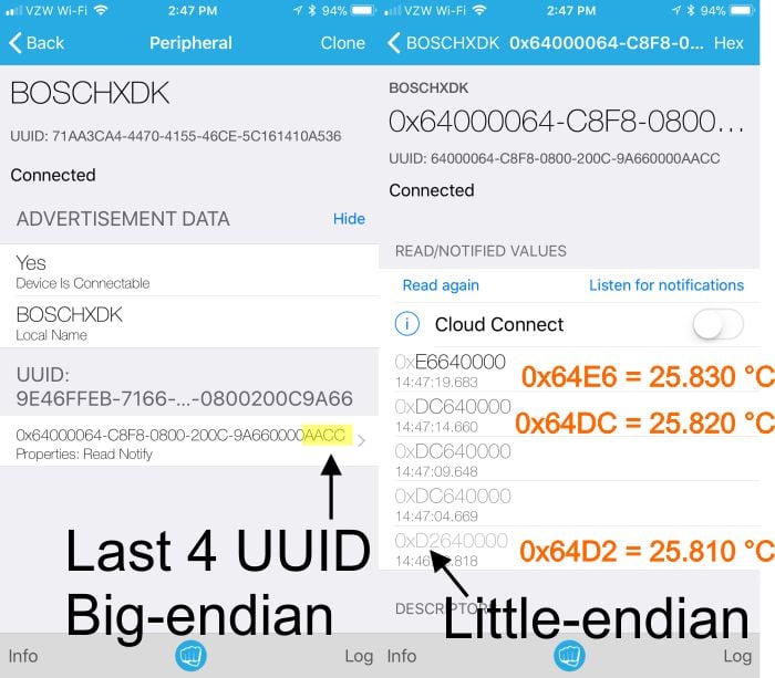
The data transmitted by the XDK110 in the above program is shown on the iOS app “Light-Blue Explorer.” The BLE protocol uses a combination of little and big endian formats for data—a potential “gotcha” for the inexperienced BLE programmer.
Using the XDK110 with MQTT
Message Queuing Telemetry Transport (MQTT) is a data transmission protocol designed for machine-to-machine (M2M) data transmission. A server—referred to as a message “broker”—receives transmissions from devices that “publish” information in particular “topics” and subsequently deliver those messages to other machines that “subscribe” to those specific “topics”.
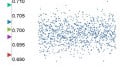
In the screenshot captured below, the XDK110 is publishing data to the topic “XDK110/example” via Wi-Fi to an MQTT broker. My computer is running the client program Mosquitto_sub.exe and is subscribed to the topic “XDK110/example” on the same MQTT broker. All data that is published by the XDK110 is shown on my computer in the console.
Any number of devices can publish and any number of devices can subscribe to available topics on a broker server. In most cases, the data is not maintained on the server. Quality-of-service settings provide a means to verify that messages have been received after transmission.
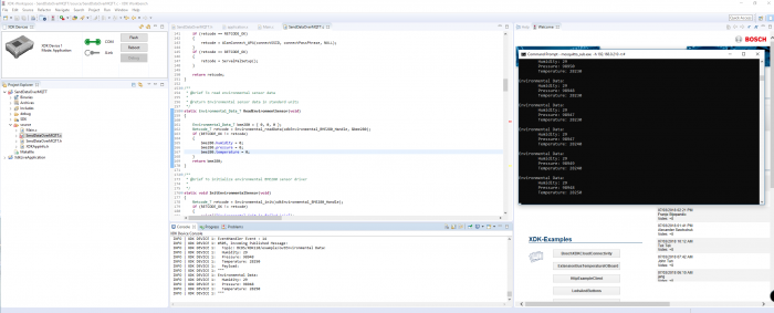
Screenshot shows debug data sent back over virtual COM port interface (center bottom “console” window) and data at the MQTT server (“Command Prompt” window).
Anyone can generate code on XDK Live; if you want to modify the generated code, though, you’ll need above-average programming expertise.
The following demo creates an MQTT client using XDK Live. Basic building blocks are used to create the structure, and the code is pre-compiled every time the file is saved.
// The following code belongs to the main package
package main;
// The XDK110 is the device used
import platforms.xdk110;

// Create a wireless connection named 'wireless'
setup wireless : WLAN {
	ssid = "AllAboutCircuits";
	psk = "BestWebsiteEver”;
	useDHCP = true;
}

// Create a MQTT instance
setup messaging : MQTT {
	transport = wireless;
	url = "mqtt://broker.hivemq.com:1883";
	cleanSession = true;
	clientId = "1234";
	var Test = topic("XDK/Test",1);
}

// When button one is pressed, send text via MQTT
every button_one.pressed {
	messaging.Test.write("Test Write");
}

// Read and transmit the temperature every 5 seconds
every 5 seconds {
	var myTemperature = environment.temperature.read();
	messaging.Test.write(`Temp: ${myTemperature}`);
}

// Read and transmit the barometric pressure every 15 seconds
every 15 seconds {
	var myPressure = environment.pressure.read();
	messaging.Test.write(`Press: ${myPressure}`);
}
Every time you modify and save the code, the software pre-compiles this abstracted code into actual code, which in turn is compiled right before you load new firmware into the device.
In short, this code snippet in XDK Live...
every 15 seconds {
	var myPressure = environment.pressure.read();
	messaging.Test.write(`Press: ${myPressure}`);
}
...generates the following function in C++:
Retcode_T HandleEvery15Second1(void* userParameter1, uint32_t userParameter2)
{
	BCDS_UNUSED(userParameter1);
	BCDS_UNUSED(userParameter2);

	Retcode_T exception = NO_EXCEPTION;

	Environmental_Data_T sensorEnvironmentModalityPreparation_0;
	exception = Environmental_readData(xdkEnvironmental_BME280_Handle, &sensorEnvironmentModalityPreparation_0);
	if(exception != NO_EXCEPTION) return exception;

	uint32_t myPressure = sensorEnvironmentModalityPreparation_0.pressure;
	char result1354933794[17];
	snprintf(result1354933794, sizeof(result1354933794), "Press: %" PRIu32 "", myPressure);

	char* _newConnectivityMQTTMessaging_Test_0 = result1354933794;
	exception = ConnectivityMQTTMessaging_Test_Write(&_newConnectivityMQTTMessaging_Test_0);
	if(exception != NO_EXCEPTION) return exception;

	return NO_EXCEPTION;
}
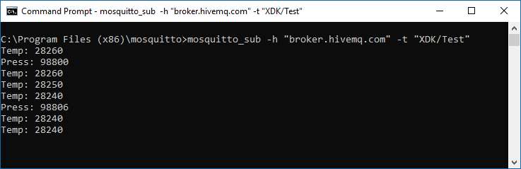
Once the code is generated, compiled, and loaded into the device, it begins communicating with a message broker.
The result is shown in the screenshot below, captured on a computer that is connected to the XDK110 only through the MQTT broker.
Virtual XDK Demo
If you want to start playing with your XDK110, the Virtual XDK iOS and Android apps are a good place to start. The code required for the XDK110 is available from the welcome screen under “VirtualXDKDemo”—it creates a BLE peripheral that transmits all available sensor data to a mobile phone for viewing.
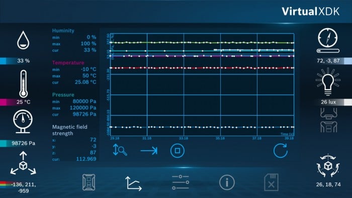
VirtualXDK iOS app shows available sensor data and graphs it over time.
Conclusion
All-in-one sensor solutions are designed to instantly upgrade an apparently antiquated device into something that may be equivalent or even preferable to a newly purchased product. It's worth noting that other platforms, such as the Nordic Thingy, offer similar functionality. The XDK110 is one example that has a software ecosystem that facilitates efficient integration into existing equipment.
If you've worked with the XDK110 or a similar sensor development board, share your experiences in the comments below.


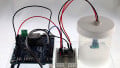


I’m new to electronis. Can anyone heIp me with a circuit that would run on two LDR working alongside one another. Each LDR trap its own light, if one LDR is having higher impedance, pinA goes high and pinB; low, otherwise pinB becomes high and pinA; low. But if they happen to be the same impedance, pinA and pinB becomes low
Hello, i’m working on XDK110 and i found that article. However, i got a question : How can i stream Noise Sensor data please ? I’ve found nothing about it on the internet and the whole documentation. Thanks.