 Facebook
 Google
 GitHub
 Linkedin
How to Build a Real-Time Clock with a PICAXE
Teaming up a PICAXE µC, a DS1307 real time clock module, and an LCD117 serial adapter with a liquid crystal display is a fun, educational way to assemble your own date and time demo.
Introduction
Adding a real time clock (RTC) circuit and a digital display to a microcontroller to create a functional clock is a favorite undertaking for many electronics DIYers. In fact, an excellent such project using an Arduino was recently published in Jens Christoffersen's article here on AAC.
This project presents a different, and perhaps somewhat simpler approach that uses a PICAXE 08M2+ microcontroller, an LCD with a serial backpack as documented in this article, and a real time clock module.
Building and programming this design requires a modest background involving PICAXE microcontrollers, and if you find yourself underequipped, a review of some of these articles may be in order.
Real Time Clock Modules
A real time clock module consists of an RTC integrated circuit plus the peripheral components necessary to support the clock chip, all of which have all been assembled on a custom printed circuit board. A example of such a module is shown in the photograph below.
.png)
This particular RTC module is the author's own design, but is more or less representative of many other designs. At the top center is the RTC chip which, in this case, is a DS1307 from Maxim Integrated. To the left of the DS1307 is a 32.768 MHz crystal, and below the crystal is a 3V backup battery to keep the DS1307 running when external power is interrupted. The green LED lights to show that external power is connected, and the ceramic capacitor filters the power to the DS1307. The pin header labeled "PH5" connects the module to power and other external circuitry. The three resistors are pull-ups for three of the signal leads.
Why a DS1307?
The DS1307 is not the newest RTC around, nor is it the most accurate, so why use it? There are two main reasons: first, it is widely used and available at very low prices, and second, it uses I2C (say "eye squared see") signalling. A quick on-line search will locate DS1307 modules from US and international suppliers. Some modules will have only the DS1307 IC, and others may add an AT24C32 or some other EEPROM chip; the programmable memory isn't used in this project, but it won't cause any problems if it's included.
I2C signalling is mandatory for the code in this project. It requires only two wires for communication with the microcontroller: a serial data line (SDA,) and a serial clock line (SCL,) and both are potentially bi-directional. There is lots more to learn about I2C, and you are encouraged to look into it, but an in-depth knowledge is obviated by the amazing capabilties of the PICAXE system.
In general, any RTC module is usable for this project as long as it meets the following requirements.
- Uses a DS1307
- Operates on 5VDC and provides connection points for +5Vin and ground
- Provides easy access to the SDA and SCL leads
Header pins are often used as connecting points; see the photo below. (Access to the Vbat and SQW leads is not required.)

Of course, you can also build your own RTC circuit as described here as long as it meets the requirements stated above.
Circuit Diagram and Breadboard Assembly
The circuit diagram is shown below; click here for a larger image.
As you see, the circuit is quite simple. The RTC module comprises all the parts inside the red rectangle, and is connected via four wires to the PICAXE. The display is equipped with an LCD117 serial backpack adapter, which is connected to the 08M2 by only three wires via PH1.

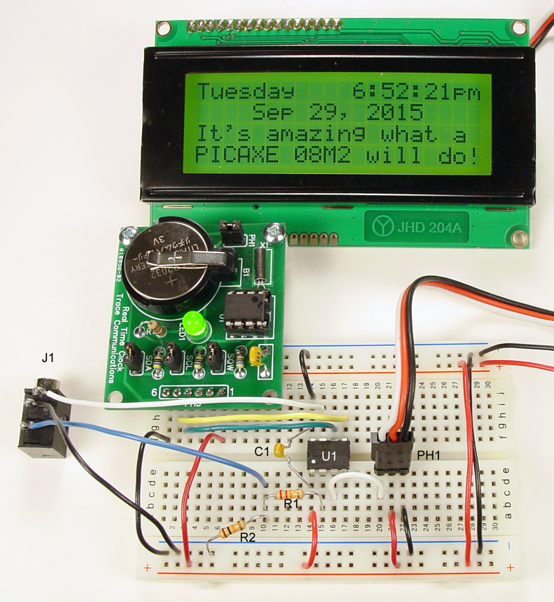
The photo below shows the the RTC module, the solderless breadboard assembly, and the display; the project is fully functional. Note that the wire colors noted on the schematic above correspond to the actual wire colors that were used in the solderless breadboard assembly.
Of course the physical appearance of your assembly will vary from the photograph to accommodate the DS1307 RTC module you use. The electrical configuration should be identical to both the schematic and the photograph.
What About the Code?
Like all PICAXE projects, this one depends upon code written in PICAXE BASIC and composed in one of the IDEs (Integrated Development Environments) available free at the PICAXE website. PICAXE Editor 6 is the most current IDE, and is highly recommended.
Two fully functional programs are available for you to download and run. Please download them both, and open them both in PICAXE Editor 6, but don't program the 08M2 with either one just yet.
The first is used to load the day, date, and time into the DS1307, is very short, and is shown below. It is reasonably well commented, but will be discussed later in this article.

The second program is used to read the day, date, and time into the PICAXE 08M2, and provide instructions to the µC to convert, format, and display the results on the LCD. Due to some of the line lengths, it cannot be displayed at full size; click here for a larger image. You can download it, and open it with Program Editor 6, but don't program the 08M2 with it yet.

Programming the PICAXE
Making the clock functional requires two programming operations. First, DS1307 24-Hr Time Set.bas must be programmed into the 08M2, which sets the time, day, and date in the DS1307. Second, PA-08M2+ LCD117 RTC.bas is programmed into the PICAXE to instruct the µC how to read the DS1307, convert the data, and display the corresponding time, day, and date on the LCD.
If you haven't already done so, start PICAXE Editor 6 (or the IDE of your choice) and open both programs. Note that DS1307 24-Hr Time Set.bas will load an incorrect date into the RTC chip; do not change it at this time. Program the 08M2 with DS1307 24-Hr Time Set.bas, and when it has completed, program the 08M2 with PA-08M2+ LCD117 RTC.bas.
If all is well, after about six seconds the LCD should display the time as just before midnight on Saturday, December 31, 2011. Watch as the clock reaches midnight; the day changes to Sunday, the date changes to January 1, 2012, and the time changes to 12:00:00 am. Put on your New Year's party hat and celibrate your new functional clock.
Resetting the Clock
Setting the time, day, and date in the DS1307 is as simple as modifying DS1307 24-Hr Time Set.bas, and reprogramming the circuit. Line 18 contains eight pairs of hexadecimal numbers, and line 19 is a comment that shows what each of the pairs controls. The first seven pairs are used to set the time, day, and date; compare the values inside the parentheses with the comments in lines 11, 12, and 13.
Change the hexadecimal values inside the parentheses to reflect the time, day, and date you want to load in the DS1307. It is probably best to set the time a minute or so later than the actual time in order to allow yourself time to be ready to program the PICAXE. And because it takes about 15 seconds to program the chip, you should start the programming about that long before the time you have chosen.
Also, remember that after you use DS1307 24-Hr Time Set.bas to reset the time, you will need to program the PICAXE again with PA-08M2+ LCD117 RTC.bas.
Want to Know More?
If you are content with having a clock that works, that's great; read no further.
But maybe you are wondering why the display on the clock shows a 12-hour format when the DS1307 was programmed to use a 24-hour format. Or maybe you are puzzled why the time, day, and date was programmed in hexadecimal numbers, but the display shows decimal numbers. Or perhaps you have other questions about the code's operation.
Both programs are reasonably well commented and the methods used to convert the data from the DS1307 are fairly well known, but frankly, there are some operations that can't be fully explained in a comment. In fact, such explanations are beyond the scope of this project, and would require an article of their own. However, the DS1307 datasheet contains a wealth of information, and the bcdtoascii command is described in PICAXE Manual 2.
Good luck, and happy tinkering!
Give this project a try for yourself! Get the BOM.
Related Content


found this very helpful thank you
Can not load an image (png) file into the PE6 IDE. There is some code to program the DS1307. Where’s the code for the Serial clock?