 Facebook
 Google
 GitHub
 Linkedin
Build a PICAXE ESP-01 Wi-Fi Communicator
A PCB for a Wi-Fi communicator using a PICAXE 08M2 and an ESP-01 module driven by interactive code makes a handy setup for data collection and IoT reporting.
What's New?
A previous article described the solderless breadboard construction of a circuit and the associated software to allow a PICAXE 08M2 microcontroller to take a temperature reading from a DS18B20 IC, connect via an ESP-01 module to a local Wi-Fi access point, connect to Thingspeak.com, and store the data in a channel for display. If you haven't read that article, you should do so because there is information included there that will not be repeated here.
This article improves the project in the following ways.
- The need for specialized pin arrangements for the ESP-01 is eliminated.
- The circuit design is improved to reduce the current required.
- The code is improved to make it interactive with Thingspeak, and reduce the reporting time to 15 seconds or less.
- Information is provided for buying a PCB (Gerber files,) and for making a PCB (trace layout drawings.)
- Options are suggested for additional circuit flexibility.
The Circuit Schematic and Assembled PCB
The PICAXE Wi-Fi Communicator is a relatively simple circuit with a low parts count, and no SMD components are used. The schematic diagram is shown below.

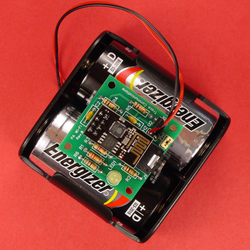
Two views of the assembled PCB are shown below: one without the ESP-01 module inserted in to the board-mounted jack, and one with it inserted. The component designations on the schematic drawing match those on the PCB. Note that the power supply wires are to be connected to the PH2 pads, and PH1 functions as an on/off switch for power to the assembly.

The photograph below shows a fully assembled board connected to its D-cell alkaline battery pack.
Parts Required
| Reference No. | Description | Qty. | Source | Part Number |
|---|---|---|---|---|
| J1 | Jack, 3.5mm, 3 Conductor | 1 | Digi-Key | SC1458-ND |
| R1 | Resistor, .25W, 22kOhms | 1 | Digi-Key | 22KQBK-ND |
| R2, R4, R5 | Resistor, .25W, 10kOhms | 3 | Digi-Key | 10KQBK-ND |
| R3 | Resistor, .25W, 4.7kOhms | 1 | Digi-Key | 4.7KQBK-ND |
| R6 | Resistor, .25W, 560Ohms | 1 | Digi-Key | |
| C1, C2 | Capacitor, Ceramic, 50V, .1µF | 2 | Digi-Key | BC2665CT-ND |
| U1 | Microcontroller, PICAXE 08M2 | 1 | P.H. Anderson.com | PICAXE-08M2 |
| U2 | Sensor, Temperature, DS18B20 | 1 | Digi-Key | DS18B20+-ND |
| N/A | Socket, IC, 8 Pin, Solder | 1 | Digi-Key | ED3044-5-ND |
| LED1 | Diode, Light Emitting, T1 3/4, Yellow | 1 | Jameco | 697696 |
| PH1, PH2 | Header, Pin, Straight, 40 Position (Make from strip.) | 2 | Jameco | 2168211 |
| N/A | Header, 2x4 Female, 2 Row, 8 Position | 1 | on-line search | See text. |
| N/A | Shunt, 2 Position, .1" Centers, Closed | 1 | Jameco | 112432 |
| N/A | Battery, 1.5V, Alkaline | 2 | local | See text. |
| N/A | Holder, Battery, Dual | 1 | local | See text. |
| N/A | Module, ESP-01 | 1 | on-line search | ESP-01 |
| N/A | Cable, PICAXE, Programming, USB | 1 | P.H. Anderson.com | AXE027 |
|
N/A |
Printed Circuit Board, Custom Made, FR4, 1.6mm Thick, 1 oz. CU | 1 | Itead or Home Fabricated | See text. |
ESP-01 Firmware Update
Many ESP-01 modules lack a current firmware version, and should be updated prior to use in this project. The process for flashing an ESP-01 module is detailed in this article, and should be followed carefully to bring the firmware up to date, and ensure compatiblity with the PICAXE code used in this project.
In order to flash the ESP-01 firmware, you will need a circuit to provide power to the module as well as to connect it to your computer. A suitable flash circuit schematic is shown below, and a solderless breadboard assembly is also pictured. The wire colors indicated on the schematic are the same as the corresponding wires on the solderless breadboard.

All power for the breadboard is supplied via the USB to TTL converter, which must be set to 3.3V in order to avoid damaging the ESP-01 module.
The small piece of green perfboard is an adapter that allows the ESP-01 to be inserted correctly into the solderless breadboard. The white numbers on the female pin header correspond to the ESP-01 pin numbers in the above schematic. (The inset shows the ESP-01 inserted in the adapter.) Note that it is also possible to use individual fly wires to connect the ESP-01 module to the breadboard. However you choose to make the physical connections, ensure that they agree with the schematic diagram shown above.

The Printed Circuit Board
The printed circuit board for the PICAXE Wi-Fi Communicator was created based on a schematic drawing and a PCB layout designed with a software program called DipTrace. DipTrace was then used to create Gerber files for the design that were sent for prototyping to the manufacturer in China, a company named Itead. Itead manufactured 10 of the PCBs and shipped them to the US for a total cost of about US$14; it took approximately three weeks from the time they were ordered until they arrived.
The original DipTrace schematic drawing and PCB layout files are available for downloading for those of you who want them for use in making your own PCB. In addition, the Gerber files are also available for those who want to order PCBs from Itead or another supplier. These files are for hobby use only and are not to be used for any commercial purpose. The author has successfully used these files and believes them to be correct and suitable for the purpose of producing functional PCBs as shown and described in this article, but there is no guarantee; use them at your own risk.
PA-08M2_ESP-01_Wi-Fi_Communicator.zip
Assembly
Assembly of the PICAXE Wi-Fi Communicator is easy; just follow the reference designations on the PCB and install the correct components from the parts list. Generally, it is easier to install and solder the shorter components first.

The set of parts is shown above, and the suggested order of installation is as follows.
- all resistors (Note that 560 ohms is quite high for current limiting resistor R6, but it helps to minimize the battery drain. If you want the LED to be brighter, reduce the value of R6 to 120 ohms, which will result in about 10mA of current.)
- both capacitors (Note that either radial lead or axial lead ceramic capacitors may be used.)
- the 8-pin DIP socket (Make sure the socket is installed to match the outline on the PCB; pin 1 goes to the rectangular pad.)
- the programming jack (The jack may be left off if you are sure you will not want to program the PICAXE while it is on the Communicator PCB.)
- the DS18B20 (Wires may be soldered in the U2 pads if U2 is to be located off the PCB.)
- the LED (The LED may be left off [along with R6] if desired.)
- the 8-pin female header for the ESP-01 (Two 1x4 female headers may also be used. Alternatively, the ESP-01 module could be soldered directly to the PCB, however, this will make it very difficult to remove the PICAXE chip as well as the ESP-01 Module, and is not recommended.)
- PH1 (This header is used as an on/off switch for the Communicator; connect the pins together with a shunt to power up the assembly.)
Power
The ESP8266, which is the main IC on the ESP-01 module, is designed to run on 3.3V, and anything higher may ruin the chip, so a good power source is critical. One option is a clean, well regulated DC power supply as described here, but another viable choice is a battery supply. Two 1.5V cells in series will work, and the choices are plentiful. The photo near the beginning of this article shows the assembly powered by two alkaline D cells, which provide extended operating time compared to smaller cells such as AA or AAA.
During the time the Communicator is reporting to Thingspeak, it draws about 150mA depending upon how high the transmitter power is set in the ESP8266. However, most of the time the PICAXE 08M2 has the ESP-01 in standby, and power drain is less than 1mA. With a duty cycle of 15 seconds reporting and 3585 seconds in standby out of every hour (as controlled by the code,) a fresh pair of alkaline D cells should last close to a year. That's a real benefit if you intend to use the Communicator in a hard-to-access place such as an attic or a crawlspace.
One critical note is that the Communicator has no built-in protection against power polarity reversals, so be certain to connect the DC supply with the polarity as shown in the photographs and the schematic drawing. The V+ goes to the top pad on the PH2 header, and the ground goes to the lower pad; see the photo in the second section of this article and the photo below.
.png)
The PICAXE Code
Download the code for this project and open it in PICAXE Editor 6.
PICAXE_Wi-Fi_Communicator_(redacted).zip
As you see, the code is well commented, linear, and relatively simple; thus, a lengthy explanation here is unnecessary. Read all the comments carefully and follow them exactly as you make changes to include your LAN SSID and your LAN password in line 49, and your Thingspeak write key in line 75. With these three changes, the code should run as written. Note that you will be able to see the code's progress in the PE6 terminal window.
Install the code in the PICAXE 08M2 and try it out. Any failures will likely be due to insufficient wait time; lengthen the wait time in the failing step.
Options
This project employs the DS18B20 temperature sensor, but other possiblities exist for the enterprising user.
Notice that the three pads on the PCB for the DS18B20 connect to +V, ground, and pin C.1 of the PICAXE 08M2. This not-so-coincidental fact opens up the possiblity of using a three-wire cable to locate the DS18B20 off the PCB, which is a benefit, but it also enables some addtional options thanks to the flexibility of the 08M2. Pin C.1 can be a digital input, a digital output, an ADC input, or a touch input.
For example, suppose instead of measuring and reporting temperature, you wanted to measure and report light intensity. In that case, you could construct a small circuit consisting of an LDR and a resistor in a voltage divider configuration, and connect it via a three-wire cable to the U2 pads on the Communicator PCB. You would need to remove R3 from the PCB, and modify the code to use pin C.1 as an ADC input to read the voltage and convert it to a digital value for storage and reporting to Thingspeak — relatively simple changes for a PICAXE afficionado like you.
Many possibilities exist. What can you imagine and build?
Give this project a try for yourself! Get the BOM.


It’s a compatible and easy project.i like it
Thank you, Charles!! The Picaxe IoT articles are great. I’ll be incorporating an ESP-01 into the control panel (picaxe controlled) for my Thermal Solar, then I’ll be able to monitor it wherever I have WiFi!