
 Facebook
 Google
 GitHub
 Linkedin
Building a Push-Pull Level Shifter to Connect an MCU and a Low-Voltage Display
In this project, we'll build and demonstrate a discrete analog solution to the incompatible logic levels of an Arduino Uno and an Elecrow e-paper HMI display.
Quite often, embedded hardware engineers are faced with the challenge of interfacing devices that operate at different logic levels. For example, consider the problem of wiring a microcontroller with a 5 V output port to a programmable unit or controller with a 3.3 V input port. This scenario is illustrated in Figure 1.
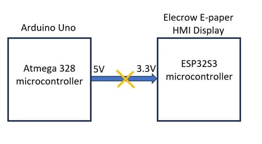
Figure 1. How do we solve the problem of interfacing a 5 V logic device to a 3.3 V programmable unit or controller?
To resolve the incompatibility issue, we can use a voltage level shifter. This typically takes the form of an integrated circuit (IC). However, that's not the only option. As we'll soon see, a discrete analog circuit can easily accept a 5 V control signal and safely shift a 3.3 V output voltage.
In this project article, we'll use a pair of transistors to build a push-pull level shifter. We'll then demonstrate its effectiveness by using it to solve exactly the problem illustrated in Figure 1: wiring a 5 V Arduino Uno to an Elecrow e-paper HMI display.
Before we start discussing the level shifter's operation, however, let's briefly go over how e-paper technology works.
Understanding the E-Paper Display
Electrophoretic display technology, also known as e-paper, is a low-power display system that mimics the appearance of ink on paper. Each pixel in an e-paper display contains microcapsules filled with charged pigment particles suspended in a clear fluid. When a positive or negative voltage is applied across these microcapsules, the pigment particles move to the top or bottom of the capsule, making the pixel appear either white or black. Figure 2 illustrates the microcapsules' operation.
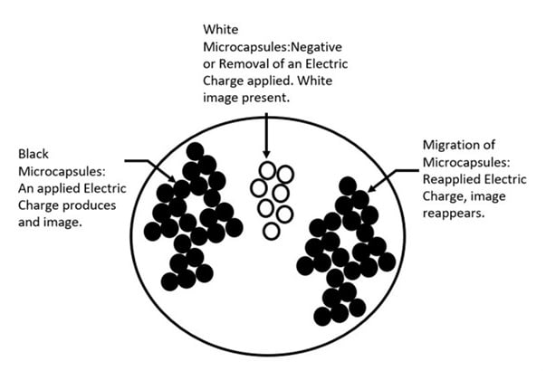
Figure 2. In e-paper technology, microcapsules are used to create images.
Because the display relies on physical particle movement rather than continuous backlighting, e-paper consumes power only when the image changes. Otherwise, the image formed by the particles is retained indefinitely without additional energy consumption. This significantly extends the external battery's charge.
The Elecrow e-paper HMI display used in this project integrates the electrophoretic layer with an onboard ESP32S3 microcontroller and a communication interface driver IC. A serial peripheral interface (SPI) enables the e-paper to receive images from the microcontroller.
The e-paper display driver operates at 3.3 V logic levels, which aligns with the ESP32S3 microcontroller general-purpose input/output (GPIO) pins. Additional GPIO pins are available for external interface and control of the e-paper display through the dual-in-line female header connector (Figure 3).
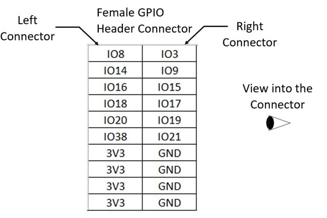
Figure 3. The Elecrow e-paper display's female header connector.
The Push-Pull Voltage Level Shifter: Schematic and Basic Operation
The circuit schematic for our project is shown in Figure 4.
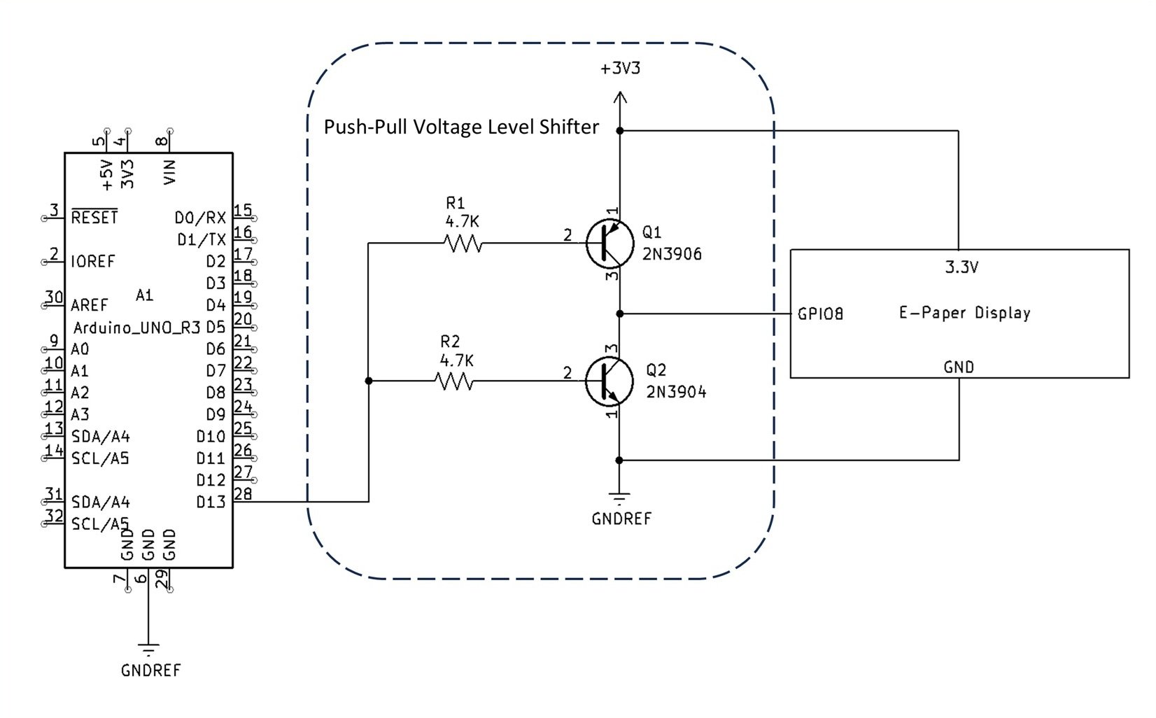
Figure 4. [click to enlarge] The push-pull level shifter circuit interfaced with the e-paper display and the Arduino Uno.
The push-pull level shifter consists of a complementary transistor pair:
The transistors are arranged so that one device sources current to the output while the other sinks it. The bases of both transistors are driven from the Arduino Uno's digital output through individual 4.7 kΩ base resistors (R1 and R2). The output of the circuit, which connects to the e-paper display input pin, is taken from the common collector node of both transistors. This node toggles between approximately 3.3 V (logic HIGH) and 0 V (logic LOW), depending on the input state of the Arduino Uno.
When the Arduino Uno output is HIGH (5 V), Q2 becomes forward-biased. This means that its base-emitter junction voltage, VBE(Q2), exceeds 0.7 V. Transistor Q2 saturates, pulling the output close to ground (LOW). At the same time, the high input voltage reverse-biases Q1, turning it OFF.
When the Arduino Uno output goes LOW (≈ 0 V), transistor Q1 becomes forward-biased since its base-emitter voltage (VBE (Q1) ) exceeds 0.7 V. This allows current to flow from the 3.3 V supply through Q1 to the output, producing a logic HIGH around 3.1 V. In this way, the circuit inverts the logic state of the input while safely converting 5 V logic to 3.3 V logic.
Circuit Analysis and Simulation
Next, let's examine the relationship between the level shifter circuit's voltage and current parameters. The parameters are as follows:
- VCC = 3.3 V
- VIH = 5.0 V
- VIL = 0.0 V
- R1 = R2 = 4.7 kΩ
- VBEon = 0.7 V (700 mV)
- VCEsat ≈ 0.2 V (200 mV)
IB(Q2) for an input HIGH (5 V) is:
$$I_B(Q2)~=~\frac{V_{IH}~-~V_{BEon}}{R2}~=~\frac{5~\text{V}~-~0.7~\text{V}}{4.7~\text{k} \Omega}~=~915~\mu\text{A}$$
Equation 1.
Assuming a conservative transistor current gain (β) of 50 in saturation, Q2's collector current is:
$$I_C(Q2)~=~\beta~\times~I_B(Q2)~=~50~\times~915~\mu\text{A}~\approx~45.7~\text{mA}$$
Equation 2.
However, the actual output current depends on the connected load. The output voltage at saturation is:
$$V_{OL}~=~V_{CEsat}~\approx~200~\text{mV}$$
Equation 3.
Since Q1 (PNP) is OFF in this state, the output is driven LOW through Q2.
For an input LOW (0 V) signal:
$$I_B(Q1)~=~\frac{V_{CC}~-~|V_{BE}(Q1)|~-~V_{IL}}{R1}~=~\frac{3.3~\text{V}~-~|0.7~\text{V}|~-~0~\text{V}}{4.7~\text{k} \Omega}~=~553~\mu \text{A}$$
Equation 4.
The transfer function of the level shifter can be approximated as a linear function:
$$V_{OUT}~\approx~V_{CC}~\times~(1~-~\frac{V_{IN}}{V_{IH}})$$
Equation 5.
Furthermore, the transfer function of the level shifter shows the inverting relationship between the input and output characteristics. This is plotted in Figure 5.
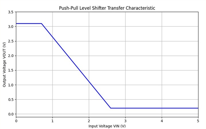
Figure 5. Transfer function of the push-pull level shifter.
Finally, let's quickly run through a QSPICE circuit simulation to illustrate the level shifter's operation. Figure 6 provides the simulation setup parameters; Figure 7 shows the output waveforms.
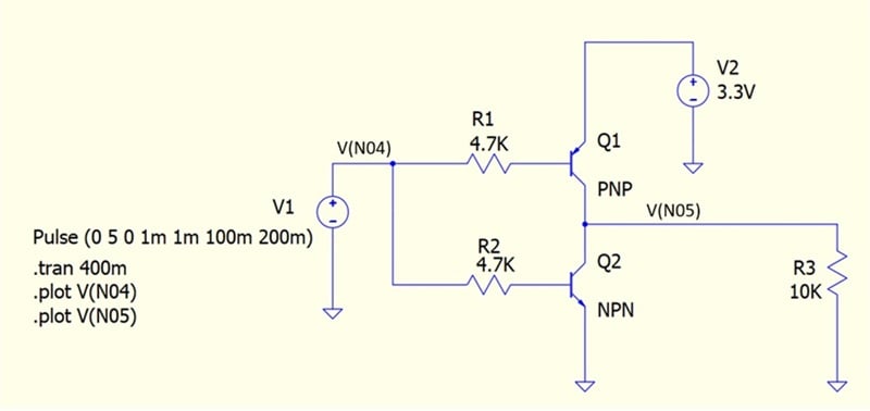
Figure 6. QSPICE circuit for simulating the push-pull voltage level shifter.
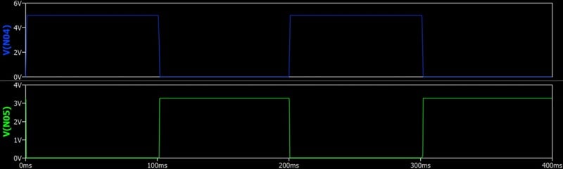
Figure 7. Simulated output of the push-pull voltage level shifter.
The result is a reliable voltage translation circuit that provides a clean 3.3 V logic signal to the e-paper display while isolating the 5 V logic domain of the Arduino Uno.
Project Build: Wiring the Arduino Uno to the E-Paper Display
Now that we understand how the level shifter operates, we're ready for the project build. To construct the interface, consult the schematic in Figure 4 and follow these steps:
- Insert the 2N3906 and 2N3904 transistors (Q1 and Q2) into a solderless breadboard.
- Connect the emitter of Q1 to the e-paper display's 3.3 V supply rail, and the emitter of Q2 to ground.
- Join the collectors of the two transistors together. This node will serve as the output that drives the e-paper display's GPIO8 input pin.
- Attach one 4.7 kΩ resistor (R1) between the Arduino Uno's digital output pin D13 and the base of Q1, and another 4.7 kΩ resistor (R2) between the same Arduino Uno pin and the base of Q2.
- Connect the level shifter circuit's 3.3 V and GND rails to the e-paper display's regulated 3.3 V source and the Arduino Uno ground, ensuring a common reference between both devices.
Figure 8 shows what the fully assembled push-pull level shifter circuit should look like once it's wired to the Arduino Uno. Verify the transistor orientations using their datasheets before powering the circuit. Reversing emitter and collector connections will prevent proper operation.
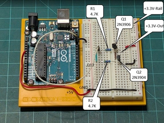
Figure 8. The fully assembled level shifter circuit wired to the Arduino Uno.
Figure 9 illustrates the e-paper display wired to the level shifter circuit.
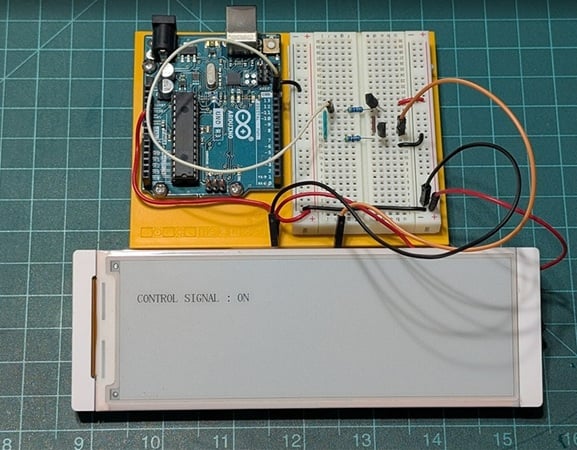
Figure 9. The completed hardware assembly for the level shifter project.
The text displayed on the e-paper in Figure 9 is part of the test code we'll install in this project's final section.
Testing the Level Shifter
To verify the level shifter's operation, upload the following test program to the Arduino Uno.
// Push-Pull Level Shifter Test Program
int controlPin = 8;

void setup() {
  pinMode(controlPin, OUTPUT);
}

void loop() {
  digitalWrite(controlPin, HIGH);
  delay(1000);
  digitalWrite(controlPin, LOW);
  delay(1000);
}
This program drives the Arduino's digital pin alternately HIGH and LOW once per second. The output of the level shifter should toggle between approximately 3.3 V and 0 V, corresponding to the translated logic levels.
To confirm this, we'll measure the output voltage with a digital multimeter. This test, which is shown in Figure 10, verifies that both transistors switch correctly and that the logic inversion behavior is consistent.
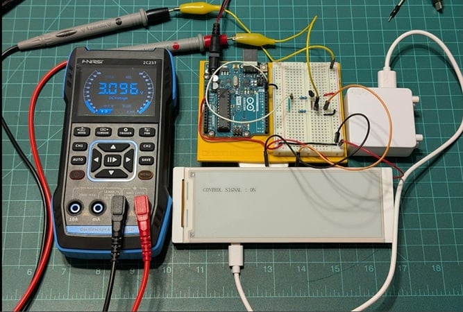
Figure 10. Testing the performance of the push-pull level shifter.
This configuration can be replicated for multiple signal lines if your e-paper display requires several control inputs (e.g., CS, DC, and RESET). Each channel will use the same transistor-resistor arrangement.
Testing the E-Paper Display
Once we've confirmed that the level shifter works, all that's left for us to do is test the e-paper display. To complete this step, you'll need to install some test code, which can be found by following this link.
After you've downloaded the code, upload it to the Elecrow e-paper display using the Arduino Uno IDE.
The test code will read the translated voltage from the level shifter circuit and respond by displaying either CONTROL SIGNAL: ON or CONTROL SIGNAL: OFF, depending on whether the Arduino Uno's digital output pin is HIGH or LOW. To see what this looks like, refer either to Figure 9 or to the video included at the end of this article.
Figure 11 shows a partial listing of the e-paper display test code.
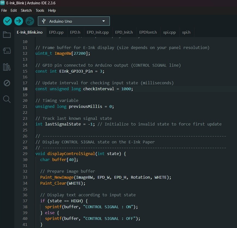
Figure 11. [click to enlarge] Partial listing of the e-paper HMI display test code.
The test code is well-commented, allowing modification to the font sizes, display messages, and image refresh switching delays.
The Project is Now Complete!
You can see the completed level shifter project in action by clicking on Figure 12.
Figure 12. Operation of the completed level shifter project (click to play video).
All images used courtesy of Don Wilcher













why not use one resistor, or to be compulsive a 2-resistor divider?