Facebook
 Google
 GitHub
 Linkedin
Controlling a Potentiometer-based Servo Motor Using a M5Stack Core
In this project, learn how to use a potentiometer's reading on the M5Stack core to control a servo motor.
The M5Stack core is a modular, stackable, and programmable development module designed for building IoT projects and creating prototypes quickly and easily. This module is based on the ESP32 microcontroller and comes with a variety of sensors, inputs, outputs, and a color liquid crystal display (LCD). Additionally, the M5Stack core is packaged as a rectangular module measuring 54 x 54 x 18 mm and has a 2-inch thin-film-transistor (TFT) LCD.
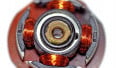
As mentioned, this unit has several input and output options, such as three push buttons, a speaker, and a microSD card slot. Figure 1 illustrates the M5Stack core.

Figure 1. M5Stack core. Image used courtesy of M5Stack
One of the most unique features of the M5Stack core is its modular design ecosystem. The module can be easily stacked with other M5Stack modules allowing users to add additional functionality and expand the capabilities of their projects. The M5Stack modular ecosystem has various modules available, such as a camera, GPS, and battery module units.
In this article, we will explore the angle sensor and servo motor units with the M5Stack core. The outcome of this hands-on project is the construction of a potentiometer-based servo motor controller with an M5Stack core TFT display.
Project Overview—Learn About Human Computer Interaction (HCI)
The M5Stack core potentiometer-based servo motor controller project will illustrate the versatility and ease with which human-computer interaction (HCI) devices can be built using off-the-shelf electronic products and software. The intent of this project is to illustrate how HCI concepts like human engagement with systems can be achieved using a small ESP32-based controller. The ESP32-based platform will have human-physical computing interaction with electromechanical objects. This project will allow the reader to understand how interaction data can be displayed and obtained from electromechanical systems using the M5Stack core’s TFT LCD. Such data can be used to explore machine learning concepts of cyber-physical systems (CPS) using programming languages like Python, PyTorch, and Pandas.
As a key technical source for this project, it is recommended the M5Stack electronic blueprints book be referenced. More specifically, chapter two, "Hands-on with M5Stack Units," provides technical insights into the electronic circuits and setup of the ESP32 modular controller and programmable sensing and control units. This book also includes hands-on projects and interactive quizzes to engage the reader. Basically, you can think of this project as an extension of the book; therefore, detailed software setup instructions will not be explained in this project.
BOM for an M5Stack Potentiometer-based Servo Motor Control
Below is a list of electronic parts to build and help explore the M5Stack core potentiometer-based servo motor controller project.
Bill of materials (BOM):
- M5Go IoT starter kit: Digi-Key part number 2221-K006-ND
- 1 KΩ resistor, 1/8 W, 5%
- 10 KΩ potentiometer
- Servo motor
- Solderless breadboard
- M5Stack electronic blueprints book (Amazon)
The M5Go IoT starter kit has a variety of sensors, jumper wires, an RGB LED, and a USB C cable. The angle sensor is included in the kit. In the project, the 10 KΩ potentiometer and the 1 KΩ resistor will be used to build a homebrew version of the M5Stack angle sensor. Chapter 2 provides details on the electrical wiring of the electronic parts on a solderless breadboard and attaching the homebrew sensor to the M5Stack core controller.
Setting Up the M5Stack Core
The project’s overall concept is to illustrate the prototype build of a small servo motor controller using the M5Stack core as the main ESP32 embedded platform. The initial setup for this project is adding an external potentiometer to control a servo motor. The potentiometer will provide rotation information to the M5Stack core. Then, the M5Stack core will convert the analog voltage division data into equivalent pulse width modulation (PWM) control signals, thereby operating the electrical wired servo motor. Figure 2 shows a system block diagram of the prototype.

Figure 2. The M5Stack core potentiometer-based servo motor control system block diagram.
Next, the potentiometer’s circuit is electrically wired to the M5Stack core’s ESP32 microcontroller using the same internal electronic components of the angle sensor. The M5Stack angle sensor is constructed using a 1 KΩ resistor wired in series with a 10 KΩ potentiometer. This circuit configuration provides a voltage division function that allows a range of discrete analog signal values to be present at a designated ESP32 analog-to-digital general-purpose input-output (GPIO) pin. Figure 3 shows the M5Stack angle sensor.

Figure 3. The M5Stack angle sensor unit. Image used courtesy of M5Stack
Furthermore, this circuit approach allows a maximum output voltage from the potentiometer with respect to ground to be +3.3 V, plus the ESP32 microcontroller’s GPIO pins are +3.3 V compliant. Therefore, the voltage divider circuit’s maximum output voltage of +3.3 V will not damage the ESP32 microcontroller. The electronic circuit schematic diagram for the homebrew angle sensor is shown in Figure 4.

Figure 4. Homebrew angle sensor electronic circuit schematic diagram.
Note that the J1 reference designator represents the four-pin female connector soldered to the angle sensors PCB.
From here, you can wire the electronic circuit on a solderless breadboard using the electrical wiring diagram shown in Figure 5 as a reference to attach the homebrew angle sensor to the M5Stack core.

Figure 5. Homebrew angle sensor solderless breadboard diagram.
Keep in mind that the M5Stack core’s TFT LCD layout can be designed using the UiFlow software—we will get into this in the next section.
Next, you will use Dupont wires to create an extension harness between the M5Stack core and the homebrew angle sensor solderless breadboard circuit. Inserting three Dupont wires, as shown in Figure 5, into the white four-pin female header connector is used to electrically interface the circuit with the M5Stack core controller. Figure 6 illustrates this electrical wiring interface connection and attachment method.

Figure 6. Solderless breadboard wiring of the potentiometer to the M5Stack core.
UiFlow Software Introduction
For this project, I used a program called UiFlow. The UiFlow is a software development platform that is designed to simplify the process of programming and prototyping for the M5Stack product of controllers, modules, sensors, and units. This software offers a graphical user interface (GUI) for programming the M5Stack core ESP32 microcontroller. Developers can drag and drop code blocks and create logical code to program the ESP32 microcontroller. The UiFlow allows coding using an online editor or a desktop downloadable software package.
The UiFlow online editor can be obtained from the M5Stack website at the following URL address here. There is a desktop version available for Windows, Apple, and Linux-based machines as well.
The layout design of the M5Stack core TFT LCD to display the potentiometer’s rotational data is shown in Figure 7.

Figure 7. Configuring the M5Stack Core TFT LCD to display potentiometer angle information.
To learn more about UiFlow, you can go to Chapter 2 of the M5Stack electronic blueprint book for additional information.
Displaying Potentiometer Readings
With the potentiometer wired to the M5Stack core, the software is needed to display the rotational values from the electrical component. The UiFlow software will be used to display the potentiometer’s rotational angle in degrees, and the code blocks consist of three major operations for the servo motor controller.
The instructional code blocks functions consist of:
- Reading the raw data from the potentiometer to a variable
- Providing an appropriate variable scaling factor to ensure proper angle display
- Displaying the angle in degrees
The UiFlow code blocks are illustrated in Figure 8.

Figure 8. UiFlow potentiometer angle display code blocks.
In addition to the code blocks, the servo and angle sensor units are included in the code block palette. These units will add a set of new code blocks for the proper operation of these devices within the overall controller product prototype. As shown in Figure 8, "servo_0, servo_0 rotate to a degree" and "get angle_0 value" are the new unit instructions added to the code block palette. You can include these code blocks by selecting the units plus button. Selecting the servo and angle units from a list of devices will add the needed code blocks to the palette to complete the code build for the project’s controller. The UiFlow code blocks will be executed on the M5Stack core by selecting the RUN button on the software’s IDE control panel.
Controlling the Servo Motor Using UiFlow
Besides displaying the potentiometer’s angle of rotation, the UiFlow code blocks, shown in Figure 8, control the servo motor. Attaching the servo motor to the M5Stack core requires the same electrical wiring technique used for the potentiometer. The partial electronic circuit schematic diagram, shown in Figure 9, illustrates the servo motor electrical wiring attached to the M5Stack core ESP32 GPIO13 pin.

Figure 9. Partial electronic circuit schematic diagram: servo motor attached to the M5Stack core ESP32 microcontroller.
The J2_A connector on the electronic circuit schematic diagram represents the A-port on the M5Stack core. While the J2_B reference designator represents the electrical wire jumper harness pins inserted into the servo motor’s black three-pin female connector.
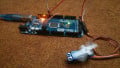
The electrical wiring of the M5Stack Core to the servo motor is shown in Figure 10.

Figure 10. The servo motor is electrically wired to the M5Stack core.
The completed M5Stack core potentiometer-based servo motor controller prototype is shown in Figure 11.

Figure 11. Final M5Stack core potentiometer-based servo motor controller prototype build.
As a final reference for the project, Figure 12 shows the complete electronic circuit schematic diagram of the M5Stack core potentiometer-based servo motor controller.

Figure 12. The M5Stack core potentiometer-based servo motor controller electronic circuit schematic diagram.
Adjusting the potentiometer will rotate the servo motor to the angle position displayed on the M5Stack core’s TFT LCD. With the servo motor having a rotational sweep range of 0˚–180˚, the TFT LCD will allow such angles to be dialed in with the potentiometer and displayed accordingly. A short video clip has been provided to show the servo motor controller in operation. To see the prototype servo motor controller in action, you can see the video here, or you can watch it down below.
Prototyping Made Easy
The intentional aspect of this project was to illustrate a unique and innovative approach to using an ESP32 platform to create an HCI servo motor controller. The M5Stack core is an ESP32-based modular IoT ecosystem that allows a variety of CPS devices to be easily prototyped using off-the-shelf electronic components and units. This project illustrated how a visual programming language (VPL) can aid the developer in rapidly building a functional prototype within several minutes. With the small form factor of the M5Stack Core, small wearable controllers and human-machine interfaces (HMI) can be developed and deployed in such areas as automation, robotics, smart homes, and educational technology development arenas.
Related Content