 Facebook
 Google
 GitHub
 Linkedin
Servo Motor Control with an Arduino
You can connect small servo motors directly to an Arduino to control the shaft position very precisely.
You can connect small servo motors directly to an Arduino to control the shaft position very precisely.
Because servo motors use feedback to determine the position of the shaft, you can control that position very precisely. As a result, servo motors are used to control the position of objects, rotate objects, move legs, arms or hands of robots, move sensors etc. with high precision. Servo motors are small in size, and because they have built-in circuitry to control their movement, they can be connected directly to an Arduino.
Most servo motors have the following three connections:
- Black/Brown ground wire.
- Red power wire (around 5V).
- Yellow or White PWM wire.
In this experiment, we will connect the power and ground pins directly to the Arduino 5V and GND pins. The PWM input will be connected to one of the Arduino's digital output pins.
Experiment 1
Hardware Required
- 1 x TowerPro SG90 servo motor
- 1 x Arduino Mega2560
- 3 x jumper wires
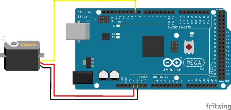
Wiring Diagram
The best thing about a servo motor is that it can be connected directly to an Arduino. Connect to the motor to the Arduino as shown in the table below:
- Servo red wire – 5V pin Arduino
- Servo brown wire – Ground pin Arduino
- Servo yellow wire – PWM(9) pin Arduino
Caution: Do not try to rotate the servo motor by hand, as you may damage the motor.
Code
When the program starts running, the servo motor will rotate slowly from 0 degrees to 180 degrees, one degree at a time. When the motor has rotated 180 degrees, it will begin to rotate in the other direction until it returns to the home position.
#include              //Servo library

Servo servo_test;    		//initialize a servo object for the connected servo

int angle = 0;

void setup()
{
  servo_test.attach(9); 		 // attach the signal pin of servo to pin9 of arduino
}

void loop()
{
  for(angle = 0; angle < 180; angle += 1) 	 // command to move from 0 degrees to 180 degrees
  {
    servo_test.write(angle);              	 //command to rotate the servo to the specified angle
    delay(15);
  }

  delay(1000);

  for(angle = 180; angle>=1; angle-=5)     // command to move from 180 degrees to 0 degrees
  {
    servo_test.write(angle);              //command to rotate the servo to the specified angle
    delay(5);
  }

    delay(1000);
}
Experiment 2
This experiment is essentially the same as Experiment 1, except that we have added a potentiometer for position control. The Arduino will read the voltage on the middle pin of the potentiometer and adjust the position of the servo motor shaft.
Hardware Required
- 1 x TowerPro SG90 servo motor
- 1 x Arduino Mega2560
- 1 x 20kΩ potentiometer
- 1 x breadboard
- 6 x jumper wires
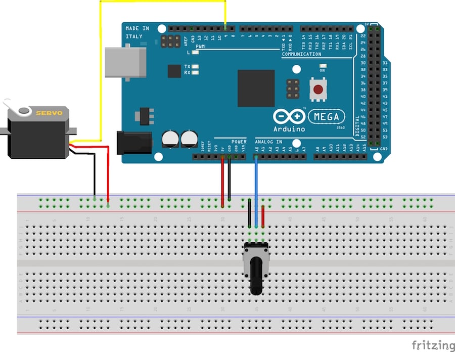
Wiring Diagram
Connect the circuit as show in the figure below:
- Servo red wire – 5V pin Arduino
- Servo brown wire – Ground pin Arduino
- Servo yellow wire – PWM(9) pin Arduino
- Potentiometer pin 1 - 5V pin Arduino
- Potentiometer pin 3 - Ground pin Arduino
- Potentiometer pin 2 – Analog In (A0) pin Arduino
Code
Once the program is started, rotating the potentiometer should cause the shaft of the servo motor to rotate.
#include         //Servo library

 Servo servo_test;    	//initialize a servo object for the connected servo

 int angle = 0;
 int potentio = A0;      // initialize the A0analog pin for potentiometer


 void setup()
 {
  servo_test.attach(9); 	// attach the signal pin of servo to pin9 of arduino
 }

 void loop()
 {
  angle = analogRead(potentio);            // reading the potentiometer value between 0 and 1023
  angle = map(angle, 0, 1023, 0, 179);     // scaling the potentiometer value to angle value for servo between 0 and 180)
  servo_test.write(angle);                   //command to rotate the servo to the specified angle
  delay(5);
 }
Give this project a try for yourself! Get the BOM.
Video for Experiment 1
Video for Experiment 2
Related Content


what power supply should i use??
I use the same code but i wait 5 sec to do the code ... and in that 5 sec he makes noise how can i use servo stoped like 3 min muted (no sound) ?