 Facebook
 Google
 GitHub
 Linkedin
How to Use MAX232 to Communicate Between a PIC and a PC
This is one simple way to control a LED, fan, relay or solenoid with a computer and a PIC.
This is one simple way to control a LED, fan, relay or solenoid with a computer and a PIC.
Recommended Level
Intermediate
Requirements
- A computer with Microchip's MPLAB X IDE, with XC8 v1.34 compiler installed. (I'm using MPLAB X v3.05 and XC8 v1.34)
- A PIC16F628A microcontroller
- A MAX232 Driver/Receiver
- A way to program the MCU
- Partslist from Eagle (see below)
- A computer with serial port interface/ a serial to USB cable
- If you want to put the circuit on a breadboard, you'll need a breadboard and some jumper wires
Introduction
Maxim Integrated Products created the MAX232 IC in 1987. It is a dual driver/receiver and typically converts the RX, TX, CTS and RTS signals from/to the PC's serial port (which can reach up to 25 v) from/to TTL levels (5 v). With a MAX232 IC you can easily connect your PIC microcontroller to your PC. This opens up a lot of opportunities. You can control LEDs, fans, relays and solenoids, to name a few. In this How To, we'll simply turn on and then turn off a LED. This may sound simple bu with this knowledge, you can already build a lot of things! You'll be needing a computer with a serial port or a serial to USB converter. I'm using a USB to RS-232 adapter. Read more about RS-232 on Wikipedia.
For a more indepth reading on USART, USART configuration and initializing, please read Microchip's: AN774 - Asynchronous Communication with the PICmicro USART. For ASM programmers, this link gives you a few source code examples.
Hardware
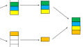
The first thing we do is make a block diagram. This is a diagram of our gadget, split into blocks. This is a good aid to keep us on track and it gives us an overlook of what we want our circuit to do.

We'll need:
- a way to program our MCU, the ICSP block
- the computer to communicate with the MCU, half duplex, the computer block
- the MCU to control the LED/Output, the MCU block
- to see the LED/ output block
The LED/output block can be LEDs, fans, relays or solenoids, or any other thing you want to control. One important matter you need to address is to be sure your MCU has a USART-port. We're using the PIC16F628A, which has one port. IC leg 7 and 8 are PORTBbits.RB1 and PORTBbits.RB2, respectively. If you are using a different MCU, you have to take that into consideration.
You'll need the components datasheet when you draw your circuit. The datasheet for the PIC16F628A can be found here. This will be your guide when you are stuck. The other IC's datasheet is here: MAX232CPE.
The hardware handshake is not considered in this schematic. To satisfy hardware handshake, you have to put some jumpers on X2:

When the block diagram is made, we'll draw the schematic:
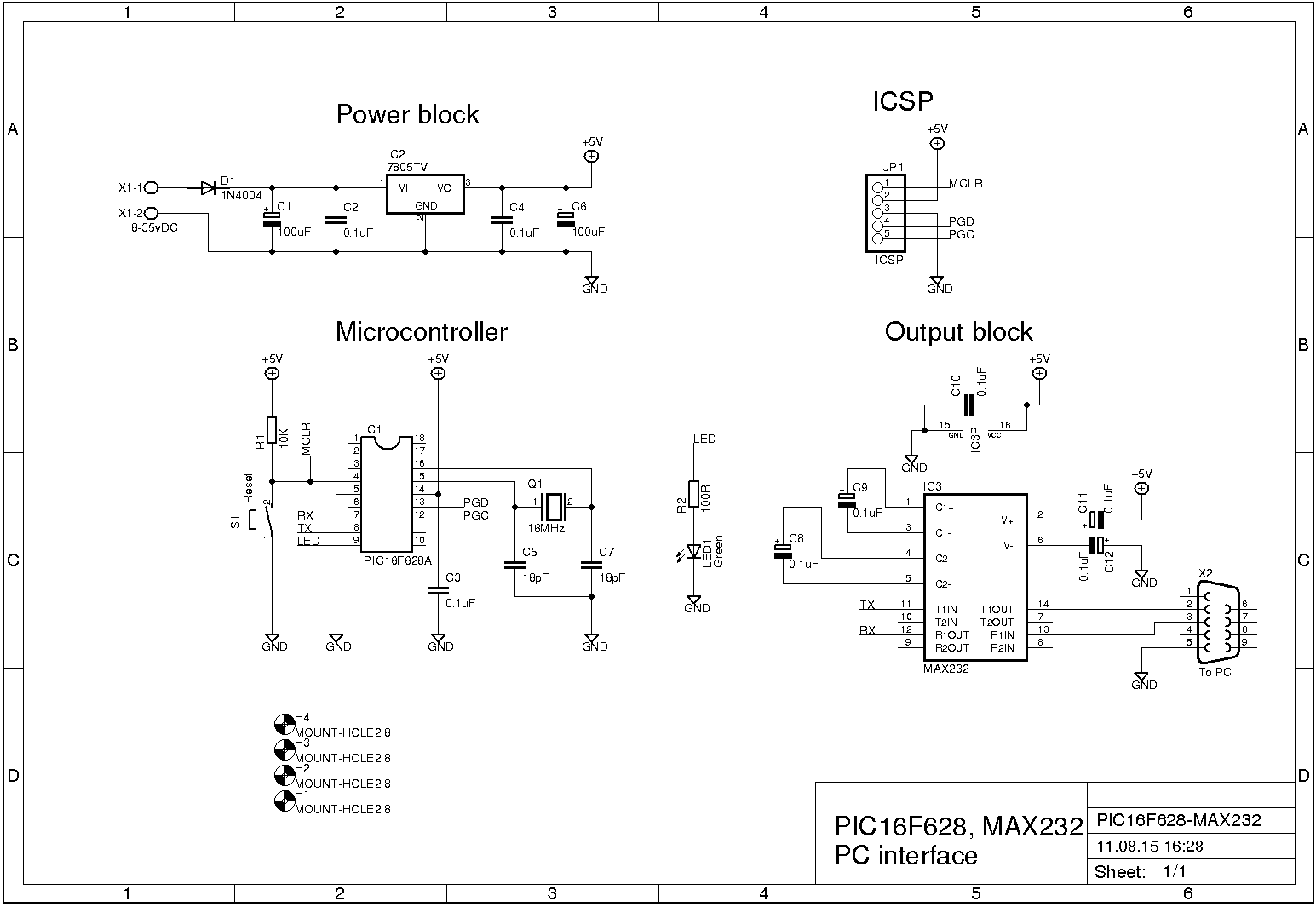
Click on image for better resolution.
Block explanation
| Block | Description |
|---|---|
| Power | This block is based on the LM7805-regulator. This is a linear regulater. With some capacitors, it regulates the volt we need to get a steady 5vDC. |
| ICSP | This is a 1x5 pin header, used to program the PIC16F628A. In this setup, I'm using a PICkit3. |
| Microcontroller | This is our PIC16F628A, the "brain". |
| Output | This is the MAX232 IC. This is connected to the PIC and to the computer. The LED is also under the output block. |
Partlist
This is a screenshot of the partlist file. The file is generated by EagleCAD.

After the hardware is made, it's time for the software.
Software
When writing software, you have to have the hardwares datasheet nearby. My setup allows me to have the datasheet on one screen while I have the programming environment on another screen. That way, I can access the datasheet in seconds.
This is based on MPLAB X IDE and the XC8 compiler. All are free for download at www.microchip.com. It is a good habit to comment on your code,while you write it. When you write it, you might think that you'll remember what all the lines do--and you may for the next day or the rest of the week. But what about a month from now? Would you still remember? Use comments. They will save a lot of work later, and others will thank you. The following code is fairly well commented, so there is no need to go through it line by line. So without further ado, here goes:
// INCLUDES
#include
#include
#include
#include

// CONFIG
#pragma config FOSC = HS        // Oscillator Selection bits (HS oscillator: High-speed crystal/resonator on RA6/OSC2/CLKOUT and RA7/OSC1/CLKIN)
#pragma config WDTE = OFF       // Watchdog Timer Enable bit (WDT disabled)
#pragma config PWRTE = OFF      // Power-up Timer Enable bit (PWRT disabled)
#pragma config MCLRE = ON       // RA5/MCLR/VPP Pin Function Select bit (RA5/MCLR/VPP pin function is MCLR)
#pragma config BOREN = ON       // Brown-out Detect Enable bit (BOD enabled)
#pragma config LVP = ON         // Low-Voltage Programming Enable bit (RB4/PGM pin has PGM function, low-voltage programming enabled)
#pragma config CPD = OFF        // Data EE Memory Code Protection bit (Data memory code protection off)
#pragma config CP = OFF         // Flash Program Memory Code Protection bit (Code protection off)

// DEFINITIONS
#define _XTAL_FREQ 16000000      // Tell the compiler that we are useing 16MHz

// GLOBAL VARIABLES
unsigned int choice;            // Variable to hold user choice
bool getchar_active = false;    // Boolean variable

// FUNCTION PROTOTYPE
void interrupt tc_int(void);
void UART_init(void);
unsigned char getch();
unsigned char getche(void);
void showMenu(void);


// FUNCTIONS
void UART_init(void){
    TXSTAbits.BRGH = 0;     // Setting BRGH to use LOW speed
    TXSTAbits.SYNC = 0;     // Setting async mode
    TXSTAbits.TX9 = 0;      // Setting 8-bit transmission
    RCSTAbits.CREN = 1;     // Enable continious receive

    SPBRG = 25;             // Setting the SPBRG register to use 16MHz with BRGH 0

    PIE1bits.RCIE = 1;      // USART receive interrupt enable
    RCSTAbits.SPEN = 1;     // Enable serial port
    TXSTAbits.TXEN = 1;     // Enable transmit

    return;
}

unsigned char getch()
{
    getchar_active = true;  // Boolean variable set to true
    while(getchar_active)   // While true
        continue;           // Carry - on
    return RCREG;           // return the value in RCREG
}

unsigned char getche(void){
    unsigned char c;
    putch(c = getch());
    return c;
}

void putch(unsigned char byte){     // Adding Carrier Return and Line feed
    while(!TXSTAbits.TRMT);
    TXREG = byte;
    if ('\n'==byte){
        while (!TXSTAbits.TRMT);
       TXREG = '\r';
    }
    return;
}

void interrupt tc_int(void){
    if(RCIE && RCIF)                // Check RC Inter bit & Inter Flag
    {
        getchar_active = false;
        RCREG;
    }
    return;
}

void showMenu(){
        printf("\n\n*****************************************************\n");
        printf("**        PIC, MAX232 and PC communication demo    **\n");
        printf("*****************************************************\n");
        printf("\n\t1. LED on.\n");
        printf("\t2. LED off.\n");
        printf("Your choice: ");
}
/*
 * THIS IS THE MAIN PROGRAM
 */
int main(int argc, char** argv) {
TRISA = 0b00000000;     // All output
PORTB = 0b00000000;     // All low

TRISB = 0b00000110;     // RB1 & RB2 set as input ref datasheet
PORTB = 0b00000000;     // All low

    UART_init();        // Initialize the UART

    INTCONbits.PEIE = 1;    // Enable peripheral interrupt
    INTCONbits.GIE = 1;     // Enable global interrupt

    do {
        showMenu();         // Show awesome menu

        choice = getchar(); // Assign char from getchar to choice

        switch(choice){     // Menu options
            case '1': printf("\n\n\t\t** Led is ON **\n");
                    PORTBbits.RB3 = 1;
                    break;
            case '2': printf("\n\n\t\t** Led is OFF **\n");
                    PORTBbits.RB3 = 0;
                    break;
            default:    printf("\n\n\t\t** Invalid choice. RTFM :-D **\n\n");
            break;
        }
    } while (choice !=3);

    return (EXIT_SUCCESS);
}
If the source code compiles with no errors or warnings, you can program the MCU, and hook it up to your computer. Open your favourite serial communication program and use 9600-8-N-1 for the port settings. Apply power to the circuit, and you should see a small menu on the screen. It works on both Windows and Linux. See the short video at the end.
Conclusion
We used a PIC16F628A and a MAX232 to control a LED with a PC. We didn't use a lot of hardware, and we didn't have a lot of code. We didn't bother to make our own libraries to write to the UART-port, either: we used the standard printf-function. Our code used 9% of the PIC's data memory and 21% of the program memory. You can download the source code from the bottom of this page.
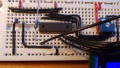
Pictures and video

The compete circuit

The microcontroller part.

The MAX232 part.
Give this project a try for yourself! Get the BOM.


Thanks! ^-^
Sweet…. Thanks for the post. This is what i have been looking for. I have a lot of max232 but i only have pic16f877a what do i need to edit on the code. Thanks
You can also email me .(JavaScript must be enabled to view this email address)
I badly needed someone to help me with my project :(