Facebook
 Google
 GitHub
 Linkedin
How to Calibrate a Microcontroller Internal Oscillator: A DIY Trimming Procedure Algorithm
This article presents an algorithm intended for humans to calibrate the internal oscillator of an MCU, with the help of an oscilloscope and a spreadsheet. An example experiment with numbers is also shown.
In the previous article titled How to Calibrate MCU Internal Oscillators, I explained the nature of the calibration techniques for internal RC oscillators in MCUs. Now, we’ll take a look at an easy procedure you can perform on your microcontrollers.
There are probably several tools to help you tune your MCU’s internal oscillator, some provided by instrument vendors, some others even intended to run on your MCU’s firmware. However, for you to fully grasp how this process works, I recommend that you follow this instrument-assisted procedure to trim your MCU’s internal oscillator. Pretend you’re at school, and take this as a lab assignment at least once!
The Calibration Procedure
To run this experiment, you’ll need a power supply, your MCU, a device programmer, a spreadsheet, and an oscilloscope, logic analyzer, or frequency counter. Let’s quickly look at the steps:
- Compile and run an application that generates a 1kHz square wave.
- Measure the actual baseline period.
- Measure the expected resolution of your trim register.
- Calculate the absolute error.
- Calculate the percentage error.
- Repeat the following steps until the desired error is reached or the required adjustment is 0.
- Calculate the required adjustment for the trim register.
- Calculate the new trimming value.
- Replace the trim register value, recompile and run, and measure the new period.
- Calculate the absolute error.
- Calculate the percentage error.
Let’s Calibrate an MCU!
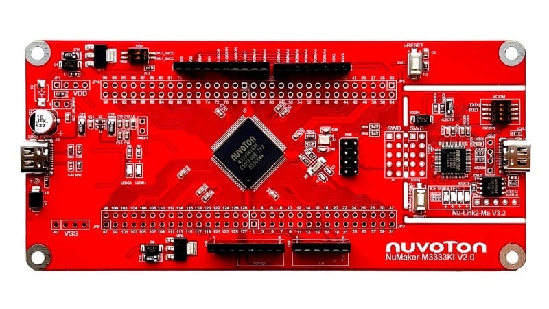
Let me show you an example of these steps performed on a brand new MC9S08SH8 microcontroller, with the 8-bit ICSTRM register described earlier. According to the manual, this register has an expected trim accuracy between ±0.2% and ±0.4%, meaning that an increase or decrease of 1 step in this register has an expected increase or decrease of 0.2% to 0.4% of the baseline untrimmed period. Since this percentage can vary in that range from chip to chip, we’ll have to measure it.
For this experiment, let’s say we want to get an accuracy better than ±0.5%.
- Run a 1kHz square wave generator.
It’s crucial to aim for a period of exactly 1ms. For this reason, you should use the tools provided by your MCU’s vendor, such as a Timer or PWM module. Use libraries and code generators, and stay away from software-based time-counting delays.
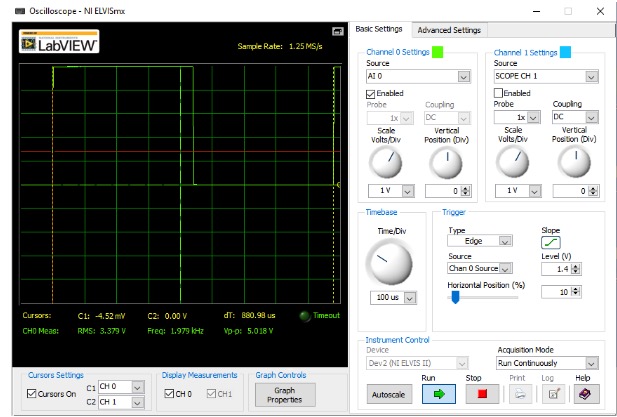
- Measure the actual baseline period.
\[T_{baseline}=880.98\mu s \]
For this experiment, I used the oscilloscope of the NI-ELVIS II suite, by National Instruments, as shown below:
- Measure the expected resolution of your trim register.
This is supposedly 0.2% to 0.4% of the baseline period, or anything between these values:
\[Resolution_{min}=Trim\:Accuracy_{min}\times T_{baseline}=0.002\times 880.98\mu s = 1.762\mu s\]
\[Resolution_{max}=Trim\:Accuracy_{max}\times T_{baseline}=0.004\times 880.98\mu s = 3.524\mu s\]
So we’ll have to measure it. To do this, we’ll measure the generated period for an ICSTRM value of 129, and calculate the drift from the baseline period. After setting ICSTRM at 129, recompiling and measuring the period, I got \(T_{baseline+1}=883.18\mu s\).
These two values show a period increase of \(Trim\:Accuracy=0.2497\%\) to finally calculate \(Resolution=Trim\:Accuracy\times T_{baseline}=0.002497\times 880.98\mu s = 2.2\mu s\)
- Calculate the absolute error.
The absolute error is how much the obtained period is above the target period. For our experiment, that’s
\[error=T_{obtained}-T_{target}=880.98\mu s-1000\mu s=-119.02\mu s\]
A negative value means that the obtained period is lower than the target period.
- Calculate the percentage error.
This is simply the absolute error divided by the target period. In our experiment, that’s
\[\% error=\frac{error}{T_{target}}=\frac{-119.02\mu s}{1,000\mu s}\times100\%=-11.9\%\]
- Repeat the following steps until the desired error is reached or the required adjustment is 0.
Initially, the error is -11.9%, so we have to start iterating.- Calculate the required adjustment for the trim register.
This is the number of units of the trim register we need to add or subtract to obtain our target period. This is calculated by converting the absolute error to trim register units:
\[\Delta_{trim\_adj}=-\frac{error}{Resolution}=-\frac{-119.02\mu s}{2.2\mu s}=54.1units\approx 54units\]
We need to approximate because ICSTRM is an integer. - Calculate the new trimming value.
\[ICSTRM=ICSTRM+\Delta_{trim\_adj}=128+54=182\] - Replace the trim register value, recompile and run, and measure the period.
\[T_{obtained}=1030\mu s\] - Calculate the absolute error.
\[error=T_{obtained}-T_{target}=1030\mu s-1000\mu s=30\mu s\] - Calculate the percentage error.
\[\%error=\frac{error}{T_{target}}=\frac{30\mu s}{1000\mu s}\times100\%=3\%\]
- Calculate the required adjustment for the trim register.
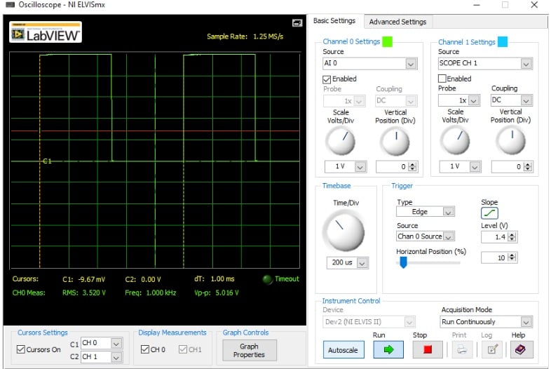
The data above shows the results for the first iteration only. After 5 iterations, the error couldn’t improve any further. Here’s the resulting output signal, where the instrument reports a period of 1ms:
The following table shows the whole process:
| Iteration | \(TRM_{old}\) | \(T_{obtained}\) | error | \(TRM_{adj}\) | \(TRM_{new}\) | % error |
| 1 | 128 | \(880.98 \mu s\) | -119.02 | 54.10000 | 182 | -11.90% |
| 2 | 182 | \(1030 \mu s\) | 30.00 | -13.63636 | 168 | 3.00% |
| 3 | 168 | \(993.39 \mu s\) | -6.61 | 3.00455 | 171 | -0.66% |
| 4 | 171 | \(999.91 \mu s\) | -0.09 | 0.04091 | 171 | -0.01% |
| 5 | 172 | \(1000.02 \mu s\) | 0.02 | -0.00909 | 172 | 0.002% |
Notice that in step 4 we reached our goal: The error dropped below 0.5%. It’s also too low for the spreadsheet to suggest a change in the Trim value, but it’s negative. It’s always a good idea to try and update the Trim value until the error starts going up again. So I tried increasing the Trim value by one in step 5, which yielded an error of 0.002%. The error is now positive, and the experiment ends; there’s no way to improve further. The value to load to ICSTRM on startup for this particular chip will be 172.
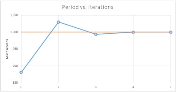
This procedure is almost deterministic. Looking at the error column, you can see how dramatically the accuracy improves: It nearly improves by one order of magnitude on each step! You can also see this improvement in the following plot.
Epilogue
Now that you’ve gone through a nice algorithm to calibrate your own MCU, remember that you don’t have to run this algorithm on your microcontrollers all the time. You should feel free to use the tools provided by your microcontroller vendor in order to make the trimming procedure easier for you.