Facebook
 Google
 GitHub
 Linkedin
How to Calibrate MCU Internal Oscillators
This article describes the internal RC oscillator calibration mechanism available in low-end microcontroller units. A basic calibration procedure and considerations on automated calibration are presented.
In the previous article titled The Good and the Bad of MCU Internal Oscillators, we exposed the benefits and drawbacks of internal RC oscillators in microcontroller units.
Now we’ll explore a technique to mitigate these drawbacks, consisting of compensating the inaccurate passive component values in the oscillator. This technique is often referred to as Trimming, Fine-Tuning, or Calibrating the internal oscillator.
Internal Oscillator Trimming in MCUs
Because of their shortcomings, internal oscillators in MCUs come with a mechanism for fine-tuning their frequency, not unlike musical instruments. This is usually done by adjusting the capacitance in the oscillator’s RC circuit by means of a miniature Capacitance Substitution Box.
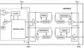
Capacitance substitution boxes contain an array of switches and capacitors to produce any capacitance within a level of precision. For example, consider the following network of capacitors which can be combined in parallel to produce any integer capacitance from 0nF to 255nF.

A capacitance substitution network.
The switches conditionally include capacitors in powers of 2. For example, closing only the three switches at the right produces 7nF. Yes, it’s binary!
Now, since RC oscillators work by charging and discharging capacitors, so these switches need to be analog. For this reason, these miniature capacitance substitution boxes use a special type of switch called transmission gates or analog switches. These are pretty much like semiconductor replacements for relays; they control digital signals and switch analog signals. There are lots of commercial transmission gate ICs like the CD4016, CD4066, and CD4053.
For more on Transmission Gates, read the article The CMOS Transmission Gate by Robert Keim.
From a programmer’s perspective, the frequency adjustment of an internal oscillator comes down to modifying the value of a memory-mapped register. The bits in this register control the switches in the capacitance substitution module.

Internal clock source trim register, widely available in the s08 family. Image from NXP.
For some members of the S08 family, this register is called ICSTRM (Internal Clock Source Trim). This is an 8-bit register, with a binary reset value of 10000000. These 8 bits control a capacitance substitution module, which in turn affects the Period of the oscillator: The higher the value of this register, the higher the capacitance and the period. This, of course, has the reciprocal effect on the frequency.
A Simple Calibration Procedure
Here’s a nice trimming procedure you may perform on your MCUs:
- Run an application that generates a 1kHz square wave.
- Iterate until no improvement is possible:
- Measure the generated signal’s period.
- Modify the Trim register towards 1ms.
- Recompile and run.
The reason to iterate is that the changes you’ll estimate for the trim register will be off by some unknown factor because of the uncertainty in the values of the capacitors in the trimming module (like a set of stairs with slightly different heights). Iterating takes care of this irregularity.
Automating this Procedure
You may want to automate this procedure for your applications so that your program calibrates the oscillator at power-on, as part of the boot sequence.
To do this, you will need a reliable clock reference to compare with a fixed frequency signal generated by your MCU. Although this may seem pointless because an external clock signal is what you’re trying to avoid in the first place, this external signal doesn’t have to meet your clock requirements; it must simply be accurate and stable.
Another important detail for an automated trimming procedure is the algorithm: The procedure described above is intended for an engineer with an oscilloscope and a nice calculator. However, many calibration functions use the successive approximation approach. This is the same algorithm used by Successive Approximation ADCs, and its essence is the binary search algorithm. Not surprisingly, this takes N iterations for an N-bit trim register.
To learn about Successive Approximation in ADCs, you may want to read the article Understanding the Successive Approximation Register ADC by Elliott Smith.
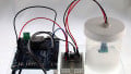
Device Programmers
There are some device programmers that provide useful additional features aside from programming ROM memories and microcontrollers. Some even perform this trimming procedure on your microcontroller for you to conveniently program a batch of devices, fine-tuning the internal oscillator on each unit.

Some device programmers are capable of calibrating the internal oscillator of their target microcontrollers.
If you’re wondering what good it does to write the correct trimming value to a RAM register when you’re about to cut the power off the device, you’re on to something!
MCU manufacturers often provide a special location in non-volatile memory to store the trimming value for your device. This doesn’t work automatically: Your code still has to fetch the value from this location at startup and write the value to the trimming register.
Epilogue
I hope to have given you a good idea of the calibration mechanism of internal oscillators, and the options you have when it comes to calibrating your MCUs.
If you’d like to try it yourself, you should read the follow-up article titled A DIY Internal Oscillator Trimming Procedure for MCUs, where you’ll see a step by step explanation, followed by an example experiment where we'll utilize a DIY trimming procedure algorithm.
Related Content