 Facebook
 Google
 GitHub
 Linkedin
A Microcontroller Enthusiast’s First Look at Programmable Logic
The FPGA can be a great addition to your arsenal, but it requires some adjustments to the way a microcontroller jockey thinks.
The field programmable gate array (FPGA) has traditionally resided in the world of high-end professional development. Until recently, FPGAs stayed almost exclusively in that arena because of the high initial cost to purchase, the expense of the development tools, and the mystery surrounding the concept. Luckily, in recent years, much of that’s changed.
FPGA Boards Are Now Within Reach
There are now quite a few reasonably priced and easy to use FPGA development boards, and the basic tools can often be downloaded for free. A few of these boards were noted in a previous article: “The Best FPGA Development Board for New Designers.”

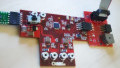
The Papilio DUO FPGA development board. Image author's own work.
However, even with FPGAs becoming more affordable and easier to use than in past years, you still might ask “why?” Aren’t microcontrollers fast and versatile enough? Maybe, maybe not.
An FPGA is essentially a custom ASIC chip that can be programmed and reprogrammed as needed. The highest capacity FPGAs have millions of gates. Most are purely digital. Some come as a system on chip (SoC), with ARM processors and analog peripherals in the same package.
It would be hard to settle on a single “best thing” that an FPGA can do. They are incredibly versatile devices, but if I had to pick a one-word answer, it would be “parallel,” as in they can do more than one thing at a time.
FPGAs Aren’t Limited to a Single Execution Path
In a microcontroller (MCU) or central processing unit (CPU), everything has to be funneled through the processor core sequentially. You can get some level of concurrency with multi-core processors, but they’re all still using the same memory bus.
An FPGA isn’t an MCU and doesn't have an MCU built into it. However, you can construct your own MCUs in the gate array. In fact, you can configure many MCUs in the gate array, creating your own multi-core processor. A more common use is to have the FPGA do the heavy computational work, while an attached MCU handles non-realtime I/O, the user interface, and other more mundane tasks.
To better understand FPGA parallelism capabilities, visualize a CPU or MCU as being run by a stack of 3” x 5” note cards. Each card has an instruction or a word of data written on it. You can duplicate any of the cards as often as you would like, and you can jump around in your stack as you see fit.
To process the instruction stack, every card has to go through a single slot, one card after the other. That slot represents the path through the MCU’s arithmetic logic unit (ALU). If you’re using a one-core processor, you’ve got just one ALU.
With each clock cycle, one card gets fed through the ALU. If you want to perform a function (a subset grouping of the cards) 5 times, you still have to feed that group of cards through the slot 5 times, each card individually. Suddenly, a 30 line function becomes 150 clock cycles of work.
“Wire Up” Groups of Logic Cells
An FPGA, on the other hand, is more like a big bag of basic logic gate chips (also referred to as “logic cells”). You can dump them out on your table and arrange and group them any way you want. So—and this is a key attribute of FPGAs—if you want to perform a function 5 times, you can create 5 discrete copies of that group of logic gates.
If your function takes 30 gates, you will need a total of 150 gates to build the circuit. But, since you’ve created a wired logic circuit, data presented to the input of the circuit propagates to the output of the circuit without being controlled by a clock. Further, since you have five circuits, one data set doesn’t need to wait for the preceding one to be completed. The entire operation, in this set of modules, takes place in a single clock cycle!

Think of FPGA Code as a Blueprint, Not as Instructions
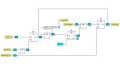
FPGA designs are created using high-level design languages, much like computers are programmed with high-level programming languages. The FPGA language code looks similar to common C code, but it acts very differently. In an MCU system, the code tells the processor what to do on each clock cycle, at runtime.
In the FPGA, the code is more of a blueprint, used at power-on. Rather than runtime instruction, the FPGA code is used to wire up and configure all of those logic gates you poured out on the table. It essentially creates a custom chip. Once the chip is powered up and configured, the code isn’t needed (until the next power-on).
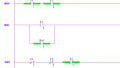
Microcontroller code in the top box, FPGA code below:

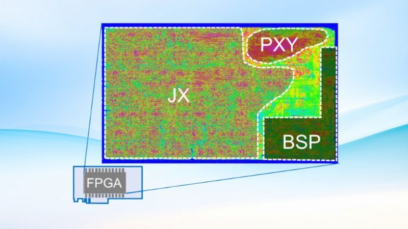
The “gate array” in an FPGA is a large array of lookup tables (LUT). The LUT is a special type of register, sometimes referred to as RAM, that is configured to simulate a logic gate. When an FPGA has been configured, the LUTs used are each mimicking a gate of some sort. Essentially, the big block of registers has turned into your grouping of logic gates.
By configuring parallel circuitry in the FPGA, nothing has been reused (unless you choose to reuse), and nothing has to go through an ALU bottleneck.
For example, consider real-time sensor fusion on a robot with 20 different sensors, each communicating via I2C.
In a conventional microcontroller system, each of these sensors must be scanned sequentially. That’s not a problem in slow-speed applications, but if it’s a fast moving bot, the entire situation could change considerably between reading the first and the last sensors. A speedy robot near a staircase could be safe when the first sensor is read, but tumbling over the edge by the time the last sensor is read.
With an FPGA, you can configure 20 independent I2C interfaces. All 20 will operate at exactly the same time. In one action, your FPGA-based bot reads all 20 sensors simultaneously. The data can be fed into the combinatorial logic that you’ve created, and presented as a virtually real-time analysis to the MCU.
A Few Downsides
FPGAs do have a few downsides. One of the biggest is the fact that FPGAs are volatile. Each time you disconnect power, it will lose its configuration. The configuration has to be reloaded at the next power up. Thus, FPGA-based devices need onboard flash, or other non-volatile memory to hold the configuration code. This makes FPGA PC boards more complex to design and build and leads to a slower start-up time. You can’t have an instant-on, single chip FPGA device.
If you’re going to look into FPGAs, there are a few things to keep in mind:
- In an MCU world, you code up a program, and then you program it into the onboard flash. In an FPGA world, it’s not referred to as a “program,” it’s a “configuration.”
- On your MCU development system, you may call the compiled code a “HEX file” or “firmware.” With an FPGA, you’ll typically refer to it as a “bitstream” or “configuration file.”
- FPGA designs are usually created using one of two languages: Verilog or VHDL. Generically, FPGA languages are called HDL, or hardware description languages. I learned Verilog, and I don’t have enough experience with VHDL to compare the two.
- In some ways, HDLs look like regular programming languages, but they aren’t. Verilog, in particular, looks quite C-like. Don’t let that fool you into thinking that you’re programming an MCU. It’ll only bring you grief.
FPGA aren't the only programmable logic game in town. CPLDs (complex programmable logic device) are similar to FPGAs, and non-volatile, but a little less flexible. Programmable logic blocks are also starting to show up in microcontrollers, such as some members of the Microchip PIC series. And, the company Silego has a family of configurable mixed-signal programmable logic devices in their GPAK line. None of these other devices reach the gate counts that high-end FPGAs do, but for simpler applications, they may be worth a look.
Conclusion
For me, the biggest change in thinking about FPGAs was the concept of the FPGA being configured at power-up time, not at runtime. If you call a function (also called a module in HDL), you aren’t just reusing a code block when running the program. With an FPGA, when the chip is powered up and the bitstream is loaded in, you’re creating individual logic circuits. When coding, it looks like software, but it’s not. It’s hardware.
With a little work, FPGAs can open up new worlds. They’re powerful, not too difficult to learn, and fascinatingly different from the microcontrollers with which most of us are familiar.


You basically proved that Arduino is better for beginner’s.
As someone who has used FPGAs in my professional life, it is good to see that there are some demo boards that are falling into the more “reasonably priced” category. These devices are very good for designs that are required to be fast, parallel and contain critical timing.
They are also a good learning platform for basic digital circuit design and can speed circuit construction considerably.
Does it fill the same niche as Arduino, well, no. Nor does it attempt to. For those that want to migrate into world of digital circuits, an FPGA is a good tool to get started. You may find that many projects do not require an Arduino.