Facebook
 Google
 GitHub
 Linkedin
Common-Mode Rejection: A Key Feature of Instrumentation Amplifiers
In this article, we’ll examine a bridge measurement system to show why an in-amp needs to have a high common-mode rejection to successfully extract a small differential signal.
Instrumentation amplifiers (in-amps) are special-purpose amplifiers designed to extract small differential signals while rejecting large common-mode signals. In this article, we’ll examine a bridge measurement system to show why an in-amp needs to have a high common-mode rejection to successfully extract a small differential signal.
We’ll also look at a special type of differential amplifiers called difference amplifiers. These amplifiers offer a very high common-mode rejection and are employed in many of today’s in-amp ICs. In the next article, we’ll see that in addition to having high common-mode rejection, in-amps should provide high and equal input impedances.
Bridge Measurement System: A Typical In-Amp Application
Consider the bridge measurement system shown below.
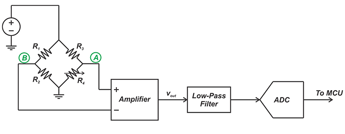
Figure 1. A bridge measurement system circuit
In this case, depending on the physical parameter being measured, the resistor R4 changes and causes a voltage difference between nodes A and B.
The amplification stage should convert the bridge voltage difference (commonly in the range of 0-20 mV) to a voltage in the input range of the A/D converter (often 0-5 V). Several different parameters of the amplifier, such as noise, bandwidth, linearity, power, and input/output swing, should be taken into account. However, there are two amplifier parameters that are of paramount importance in this particular application: common-mode rejection and input impedance.
We’ll discuss below why the amplifier needs to have a high common-mode rejection to successfully extract a small differential signal. The effect of the amplifier input impedance will be discussed in the next article.
The Bridge output Consists of Both Common-Mode and Differential Signals
The signal that appears at the amplifier inputs can be decomposed into differential and common-mode signals. For example, assume that the bridge resistor values are as shown in Figure 2.
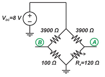
Figure 2. Adjusting our bridge resistor values
In this case, the voltage at nodes A and B will be:
\[v_A=\frac{120}{120+3900} \times 8 = 238.8\, \textit{mV}\]
\[v_B=\frac{100}{100+3900} \times 8 = 200\, \textit{mV}\]
This can be decomposed into the following differential (vd) and common-mode (vc) signals:
\[v_C=\frac{v_A+v_B}{2}= \frac{238.8+200}{2}= 219.4\, \textit{mV}\]
\[v_d=v_A - v_B = 238.8 - 200 = 38.8\, \textit{mV}\]
Hence, the bridge Thevenin equivalent will be as shown in Figure 3.
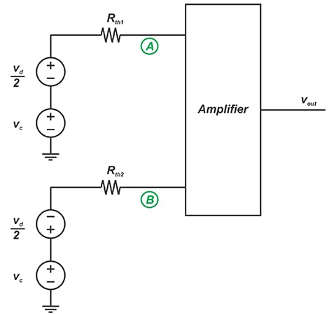
Figure 3. The bridge Thevenin equivalent
Here, Rth1 and Rth2 are the equivalent resistances of the two bridge branches and are 116.4 Ω and 97.5 Ω, respectively. Ideally, we expect the output to be an amplified version of the differential signal (that is related to the physical parameter being measured). Hence, we expect to have:
\[v_{out}=A_dv_d\]
where Ad specifies the differential gain of the amplifier. However, in reality, the input common-mode signal can also contribute to the output voltage and we have:
\[v_{out}=A_d v_d + A_{cm} v_c\]
Equation 1.
where Acm denotes the common-mode gain of the amplifier.
Why Should the Amplifier Reject the Common-Mode Signal?
With both vc and Acm being constant in Equation 1, the error at the output will be constant as well. However, the common-mode gain, Acm, can change with frequency in the bandwidth of interest. Besides, any common-mode noise that appears at nodes A and B will change vc. For example, the noise from the DC supply that powers the bridge can affect vc.
Moreover, the common-mode voltage can be a function of the bridge resistors. For example, when the bridge in Figure 2 is balanced (R4=100Ω), vc will be 200 mV rather than 219.4 mV that was obtained in the above example. Hence, the common-mode voltage can cause a varying error voltage at the output. We need an amplifier that can amplify vd while suppressing the common-mode signal.
Common-Mode Rejection of an Amplifier
An amplifier's ability to reject common mode signals is quantified by the common mode rejection ratio (CMRR), defined as the differential gain divided by the common mode gain.
Let’s take a look at some typical values. Assume that the full-scale swing at the output of the bridge amplifier is 5V and we want to keep the maximum error from the common-mode voltage to less than 0.02 % of the full-scale value (5 V). With vc=200 mV, the amplifier common-mode gain will be:
\[A_{cm}=\frac{0.0002 \times 5 \, V}{200 \, mV}=0.005\]
With a typical differential gain of 100, Acm=0.005 gives a CMRR of
\[\textbf{CMRR} = \frac {A_d}{A_{cm}}= \frac {100}{0.005}=20000=86 \, dB\]
Can a Simple Op-Amp Amplifier Provide Sufficient CMRR?
We know that op-amps are designed to amplify differential signals while rejecting the common-mode component of the input.
You might wonder if we can use a simple inverting or non-inverting op-amp amplifier to extract the weak differential signal of the bridge circuit?
Let’s examine the common-mode gain of the op-amp amplifier shown in Figure 4.
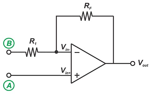
Figure 4. Example op-amp amplifier circuit
The negative feedback along with the high gain of the op amp will force both the inverting and non-inverting inputs of the op amp to have the same voltage. With the common-mode voltage vc applied to both nodes A and B, we’ll have
\[v_{in-}= v_{in+}= v_A = v_c\]
Since vc is also applied to node B, the current flowing through R1 and consequently the current flowing through RF will be zero. Therefore, we’ll have
\[v_{out}= v_{in-}= v_c\]
This means that any common-mode voltage that appears at nodes A and B will be transferred to the output with a gain of 1. With a differential gain of 100, the CMRR will be:
\[CMRR =\frac{A_d}{A_{cm}} = \frac{100}{1} = 40 \, dB\]
which is not acceptable for many applications.
What About a Difference Amplifier?
The difference amplifier depicted in Figure 5 can achieve a higher CMRR.
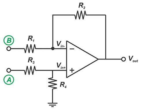
Figure 5. Difference amplifier
It can be shown that the output equation is as follows:
\[v_{out}=\frac{R_4}{R_1} \times \frac {R_1 + R_2}{R_3 + R_4} \times v_A - \frac {R_2}{R_1} \times v_B\]
With \(\frac {R_2}{R_1}=\frac{R_4}{R_3}\), we have:
\[v_{out}=\frac {R_2}{R_1}\left ( v_A-v_B \right )\]
This equation shows that any common-mode voltage will be completely suppressed by the amplifier, i.e. with vA=vB, we have vout=0. However, in practice, common-mode rejection of a difference amplifier will be limited. This is due to the fact that the ratio \(\frac {R_2}{R_1}\) won’t be exactly equal to \(\frac{R_4}{R_3}\).
For example, assume that we choose R1=R2=R3=R4 to have a differential gain of 1. Ideally, the common-mode gain should be zero. However, with 0.1% mismatch in only one of the resistors, Acm will be about 0.005 and we’ll have a CMRR of about 66 dB. Due to this limitation, we cannot achieve a high CMRR using op-amps and discrete resistors.
Instead, we’ll need to employ integrated solutions where laser-trimmed thin-film resistors deposited on the IC substrate are used to achieve a high matching between resistors. Such integrated solutions can obtain a CMRR greater than 100 dB.
Although a difference amplifier can offer a very high common-mode rejection, it still has some limitations. For example, with a difference amplifier, the impedances of the input terminals are relatively low and unequal. This leads to an unbalanced loading effect on the bridge circuit and allows the common-mode voltage to produce an error signal at the output.
In the next article, we’ll continue this discussion and see how today’s in-amps address these issues.
Conclusion
With many test and measurement systems, the desired differential signal rides on a common-mode voltage. In these cases, we need a differential amplifier with high common-mode rejection as well as high input impedance.
A difference amplifier can theoretically have infinite CMRR. However, in practice, the achievable CMRR might be limited by the mismatch between the resistor values.
Related Content