How Do Satellites Communicate with a GPS System? A Look at the GPS Antenna
Antennas provide the wireless linkage required for any satellite-based system. Here's a look at the many antennas of GPS.
Antennas provide the wireless linkage required for any satellite-based system. Here's a look at the many antennas of GPS.
Antennas are the links of GPS.
In this article, we'll go over the three segments of a working GPS antenna:
- The space segment transmits position, navigation and timing (PNT) signals, as well as satellite status.
- The control segment handles the telemetry, tracking and control (TTC) signals needed for corrections.
- The user segment receives the PNT signals and provides the GPS data we've come to rely on.
In addition, there's control of the satellite constellation itself, providing uninterrupted, continuous GPS coverage.
Let's get started.
The Space Segment: Antennas on Satellites
Antennas have always been part of satellites to transmit tracking signals since visual tracking is of limited usefulness. It took decades to reach the current GPS constellation now in orbit. Each generation (block) of satellites brought expanded functionality and improvements in antenna design.
GPS Satellite Blocks
Block I Satellites, 1978-1985
Block I satellites launched between 1978 and 1985, transmitting L1 and L2 signals. They had eight separately located antennas: two L-band antennas for the GPS signal, four S-band antennas to handle TTC data between the satellite and ground stations, and two UHF antennas to allow communication between the satellite vehicles (SVs).
Block II Satellites, 1989-1997
Block II launched between 1989 and 1997. Each group of SVs within Block II (IIA, IIR, IIR-M, and IIF) carried additional functionality. Block II SVs use multi-element arrays for the L-band signals.
The current 12-element array antenna is arranged in two concentric rings with eight elements in the outer ring and four in the inner ring. The spiral-wound helical antennas provide full earth coverage and generate right-hand circularly polarized (RHCP) signals. S-band antennas handle TTC signals, and UHF antennas allow for SV intercommunication.

Figure 1. Block II/IIA satellite antenna panel. Image from GPS.gov
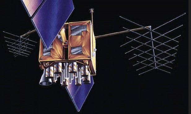
Figure 2. Block IIR satellite antenna panel. Image from GPS.gov
Block IIR incorporates a multi-element L-band antenna array and a UHF antenna assembly on the antenna panel. An S-band antenna and high and low band W-sensor antennas are included. In preparation for the IIR-M (modernized) SVs, the antenna panel was updated, which increased gain on both L1 and L2 signals.
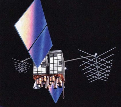
Figure 3. Block IIR-M satellite antenna panel. Image from GPS.gov
Block IIR-M transmits legacy signals L1 and L2. It also transmits the new military M-code signals on the L1 and L2 frequencies and a new civilian signal (called L2C) on frequency L2.
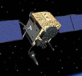
Figure 4. Block IIF satellite antenna panel. Image from GPS.gov
Block IIF transmits all the signals of the IIR-M block satellites, as well as the 3rd civilian signal, L5, the safety-of-life signal. An auxiliary receive antenna is also included.
Block III Satellites, 2018
The initial Block III satellites are scheduled for launch in late 2018 and will include a 4th civilian signal on L1 (L1C). With the launch of Block III SVs, a spot beam antenna will be included in addition to the full earth antenna array.
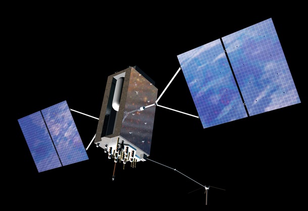
Figure 5. Block III satellite antenna panel. Image from GPS.gov
The Current GPS Constellation
The current GPS constellation is made up of 31 Block II satellites, a mix of IIR, IIR-M, and IIF. The PNT signal transmitted by each is a combination of the L-band carrier, data, its unique space vehicle number, and pseudorandom noise number (PRN) ranging code for the direct-sequence spread spectrum (DSSS) modulation.
The Control Segment: The Operational Control System
The Operational Control System (OCS) is responsible for providing control for the GPS system. It tracks orbits, synchronizes timing, and uploads data messages.
Subsystems include the AEP (Architecture Evolution Plan) which commands and controls the operational GPS satellite constellation and the LADO (Launch/early orbit, Anomaly resolution, and Disposal Operations) system which handles non-operational satellites. The OCS consists of a Master Control Station (MCS) at Schriever Air Force Base in Colorado, a backup MCS, dedicated ground antennas and monitor stations.
GPS receivers on the monitor stations passively track the navigation signals on all SVs. The MCS receives the data from the monitor stations, processes it, and sends updated navigation information to the SVs through the ground antennas using an S-band signal. The ground antennas are also used to transmit commands and receive state-of-health data (telemetry).
The frequencies used are:
- Uplink: 1783.74 MHz
- Downlink: 2227.50 MHz
There are four dedicated GPS ground antennas located at Cape Canaveral, Ascension Island, Diego Garcia, and Kwajalein Atoll. In addition to these, the control segment is augmented by ground stations around the world, including those of the US Air Force Satellite Control Network (AFSCN) and the National Geospatial Intelligence Agency (NGA). Figure 6 shows the antenna locations.
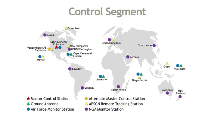
Figure 6. Control segment antenna locations. Image from GPS.gov
For Block III satellites, a new control segment is required. The OSC is scheduled to be replaced by the Next Generation Operational Control System (OSX), with initial hardware currently being verified.
User Segment: GPS Receivers
The user segment consists of all the civilian, commercial, and military GPS receivers, each equipped with internal or external antennas designed to capture the PNT signals sent from multiple SVs. GPS antennas translate the high-frequency, RHCP, spread-spectrum signal to an intermediate frequency. The antennas need a fairly small bandwidth, though receivers designed to pick up signals from other positioning systems, like GLONASS or Galileo, have extended frequency requirements. Clear sky access is needed for the best reception.
For any GPS-enabled device, whether a mobile phone, vehicle, farm equipment, life monitoring system or wearable, an antenna is required. Some people argue the antenna is the most important part of the receiver. Once received and translated, the signals in electrical form are sent for further processing... to a mapping program, tracking application or used for timing.
The availability of GPS on multiple devices has relied on the development of the microstrip antenna, manufactured as part of a printed circuit board (PCB), and the extended GPS technology developed by SnapTrack (now part of Google), meshing GPS data with wireless networks.
By integrating GPS signals with those received from sources like wireless networks and ground/satellite-based augmentation systems, GPS data becomes accurate enough to locate mobile phones for 911 use and to help pilots safely land aircraft. To use these augmentation systems, receivers must include the extra antennas and processing software for integration with GPS.
Two types of antenna have become popular in GPS receivers, the patch antenna and the quadrifilar helix (quad helix).
Patch Antennas
The name 'patch' antenna is derived from how it is constructed—a patch of metal on a ceramic substrate with feed lines. Patch antennas were initially external antennas as shown in Figure 7a, available in 5" and 2" sizes.
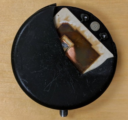
Figure 7a. External patch antenna. Photo credit: Robinson Cruz; equipment provided by Jack Skelley.
Figure 7b shows the copper on the substrate. Capable of receiving signals from satellites directly overhead, they perform best when parallel to the sky; a satellite must be above the horizon to be picked up.
Patch antennas, which function as a resonating cavity, are now manufactured as microstrip antennas. Microstrips are lightweight, low-cost, and integrated into a PCB; small enough to be designed into receivers, they offer a stable and repeatable phase center and excellent single-frequency characteristics.
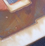
Figure 7b. Patch antenna on substrate. Photo credit: Robinson Cruz; equipment provided by Jack Skelley.
The other antenna design is a quadrifilar helix (quad helix). These antennas are rectangular and composed of four helices with 1/4 or 1/2 turn phases. They are usually external to the receiver and may be able to be used as a remote antenna (i.e., an antenna that is physically separated from the receiver and connected to it by a cable).
Figure 8 shows a Garmin GPS II, with a detachable quad helix antenna. By connecting a cable between the antenna and receiver, the antenna can be positioned for better reception. Quad helix antennas detect satellites on the horizon but do not pick up satellites directly overhead.
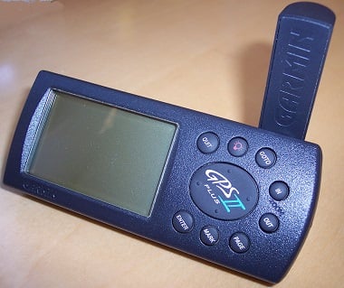
Figure 8a. Garmin GPS II with external helix antenna. Photo credit: Robinson Cruz; equipment provided by Jack Skelley.
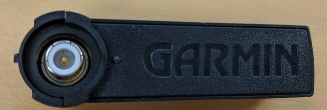
Figure 8b. External connection for remote use. Photo credit: Robinson Cruz; equipment provided by Jack Skelley.
The two antennas differ in how they are oriented. Patch antennas work best held horizontally; quad helix antennas work best held vertically. Both provide omnidirectional gain.
Antennas can be passive or active. Passive antennas do not provide additional signal processing to the received signal; they use less power and have a limited cable length. Active antennas amplify the GPS signal before sending it to the receiver to compensate for signal loss in cables. Most contain a low noise amplifier (LNA), possibly a filter and line driver. Active antennas usually improve the time needed for a lock. Both are available as microstrip antennas (along with additional circuitry, in the case of active antennas).
For environments where obtaining a GPS signal may be difficult, reradiating antennas are sometimes used. Consisting of a power supply, active antenna, transmitting antenna, and communication links, these units pick up the GPS signals and retransmit them. One use would be to have a reradiating antenna outdoors, sending the signals to indoor units.
Summary
GPS antennas, located on satellites, spread across the globe, integrated into application receivers, make possible the systems that keep us on time and on track.