 Facebook
 Google
 GitHub
 Linkedin
An Introduction to Antenna Basics
Antennas are used to transmit and receive electromagnetic energy. This article covers basic antenna theory.
Antennas are used to transmit and receive information through changes in the electromagnetic fields that surround them. This article is a primer on antenna theory.
An Abridged History of Electromagnetism
Over 2600 years ago (and likely well before that) the ancient Greeks discovered that a piece of amber rubbed on a piece of fur would attract lightweight objects like feathers. Around the same time, the ancients discovered lodestone, which are pieces of magnetised rock.
It took a few hundred years more to determine that there are two different properties of attraction and repulsion (magnetic and electric): likes repel and opposites attract. Another 2000 years passed before scientists first discovered that these two entirely different novelties of nature were inextricably linked.
In the early nineteenth-century, Hans Christen Oersted placed a wire perpendicular to a compass needle and saw nothing. But when he rotated the wire parallel to the compass needle and passed a current through the wire, it deflected in one direction. When he passed the current through the wire in the opposite direction, the compass needle deflected in the opposite direction.

A current carrying wire perpendicular to a compass needle causes no movement.

A compass needle placed parallel to a current carrying wire will rotate. When the direction of current is reversed, the direction of rotation is reversed.
This wire was the first antenna transmitter and the compass needle the first receiver. The scientists just did not know it at the time.
While not terribly elegant, it provided a clue about the way the universe worked—that charges moving through a wire create a magnetic field that is perpendicular to the wire. (Scientists soon learned the field surrounding a wire is circular, not perpendicular.)
With this information, scientists were able to describe the ways in which electric fields and magnetic fields interact with electric charges and formed a basis of an understanding of electromagnetism.
The video above shows an alternating-current lamp filament being flexed between support points in the presence of a strong magnetic field.
Shortly after, Nikola Tesla wirelessly lit lamps in his workshop, demonstrated the first remote-control toy boat, and established the alternating-current system we use to transfer electricity throughout the world today.
Less than a full century after Orstead's experiment, Guglielmo Marconi devised a way to send the first wireless telegraph signals across the Atlantic.
And here we stand, a full two centuries after that first compass experiment, able to capture images from distant planets and send them through the vastness of space to a device we can hold in the palm of our hand—all with antennas.

Image of Pluto, courtesy of NASA.
Building Blocks
Our universe came to us with certain rules. We discovered this thousands of years ago when we graduated from noticing the merely attractive force of gravity and first separated objects based on their ability to attract or repel other objects. Then we discovered another set of rules of attraction and repulsion that were completely separate from the first.
Humans categorized objects and through intense experimentation determined that positive and negative are opposite manifestations of a property called "charge" just as North pole and South pole are opposite manifestations of something called magnetism, just like left and right are two types of hands.

Image showing mirror-symmetry between electric charges, magnetic poles, and hands.
Something was happening in Orstead's wire whether he had a compass needle oriented beneath it or not. This leads to an idea of imperceivable electromagnetic fields that permeate the universe—through the densest matter and nature's best vacuums. Every one of our categorized objects (+/-/N/S) influences the space around it and is influenced if a field changes.

Magnetic field surrounding a current carrying solenoid. A Mathematica-generated image based on code by Paul Nylander.
By moving charges in predictable ways, we can change the electromagnetic fields in predictable ways and use those changes to transmit information via electromagnetic waves—regular oscillations in the electromagnetic field.
Wave Superposition
Waves transfer energy from one location to another.
Left alone over a long period of time, a pool of water will appear flat and still. Disturb the water in one location and the water molecules will disturb neighboring water molecules, which will disturb neighboring water molecules and so on until the disturbance makes it to the edge of the pool.
The molecules that started the chain of events remain close to their initial locations, but the disturbance will reach the pool's edge in seconds. Waves transfer energy without transferring matter.

Single disturbance in a pool
Waves are how we describe the movement of a disturbance through a medium. Whether through one initial disturbance or one million, the chain-reaction of molecular collisions in the pool is what drives the disturbance to propagate outwards.

Graphic of two waves in a pool
When two waves are disturbing the same region of space, their amplitudes will add or subtract to create either constructive or destructive interference. This transient additive or subtractive practice is referred to as superposition.

Graphic of wave pulse constructive interference, courtesy of the Penn State College of Engineering.
After the waves interfere in a particular location, they continue on in the same direction and the same speed that they began as long as they remain in the same medium. The speed and direction can change when a wave enters a new medium. Sound waves travel through air, water waves travel through water—the substance that waves travel through is termed the "medium".
Electromagnetic waves can travel through mediums such as air and water, or through the emptiness of space—they do not require a medium to propagate energy from one location to another.
Wave Reflection
When waves transition from one medium to another, part of their energy is transmitted, part of their energy is reflected, and part of their energy is dissipated into the environment.
The material properties of the two mediums determine the ratios of transmission to reflection and dissipation. And material properties also determine whether a wave will invert when it reflects or remain upright.
A single wave-pulse transmitting and reflecting energy. Graphic courtesy of Wikimedia.
![]()
A continuous incident wave (orange) hits an interface where some energy is reflected (light orange) and some energy is transmitted (dark orange)
Reflection and Inversion
When waves travel from one medium to another, some of the incident energy is reflected. Depending on the material properties of the mediums, waves may invert when they reflect.
Imagine a long spring tied to a pole. If you were to flick the spring to the left-of-center, the disturbance would travel the length of the spring until it hit the pole, at which point it would reverse directions and start travelling back towards you on the opposite side, right-of-center. This is an inversion.

.Gif courtesy of the Penn State College of Engineering.
Take that same spring and tie it to a rope. If you were to flick the spring to the left-of-center, the disturbance would travel the length of the spring until it hit the rope, at which point it would reverse direction and start travelling back towards you on the same side, left-of-center.

.Gif courtesy of the Penn State College of Engineering.
Understanding rope reflection helps us to understand what is happening inside an antenna.
Here are four situations that help illustrate the concepts of reflection and inversion:


Whether or not a wave inverts when it reflects is determined by the properties of the mediums on either side of the interface.
If the wave does invert when it reflects, and we want constructive interference in the rope, we must have a length of rope that is half of a wavelength long, a full wavelength long, one and a half wavelengths long and so on: $$L=n\times \frac{\lambda}{2}$$, where n is a positive integer.
Antenna resonance is based on the same basic principles of reflection and interference:
Choose a length of wire that allows reflected energy to constructively interfere to create a larger signal rather than a smaller one.
Standing Waves
When two waves of the same wavelength travel in opposite directions in the same medium (depicted in Blue and Orange in the examples below), they can interact to form a standing wave (depicted in Green in the examples below). Standing waves are so named because while the blue waves travel to the left and the orange waves travel to the right, the green standing-waves have no apparent side-to-side motion.


An incident wave (Orange) and a reflected wave (Blue) combine to form a standing wave (Green)
Standing waves only occur at specific lengths in the medium that are determined by the reflection behavior and the wavelength of the incident wave.
Standing Wave Ratio (SWR)
Standing waves of maximum amplitude occur at very precise combinations of frequency (or wavelength) and antenna length.
Unfortunately, it is impractical and actually impossible to have antennas that are the precise length to form a perfect standing wave for the desired range of operating frequencies. Fortunately, this is not necessary. A single-length antenna can function for a small range of frequencies with a small, acceptable level of imbalance.

Standing waves with net voltage shown over a period of oscillation. Image Interferometrist (Own work) [CC BY-SA 4.0], via Wikimedia Commons
Antenna length must be adjusted to create as close to a perfect standing wave as possible at the center of the operating frequency range.
SWR (Standing Wave Ratio) meters measure the ratio of transmitted to reflected energy, with the idea to have the ratio be as close to 1:1 as possible.
Small adjustments can be made by introducing passive circuit components between the final circuit amplification stage and the antenna. Small imperfections in antenna tuning will cause a potential difference to exist in the final amplification circuitry, heating the final part of the transmission circuit. Large imbalances can feed high potential differences back into the transmitter circuitry, causing dielectric breakdown and arcing.
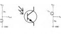
Transmitting Information
The two types of information transfer that you are likely most familiar with are FM (Frequency Modulation) and AM (Amplitude Modulation).
Frequency Modulation
With Frequency Modulation, information is transmitted by modifying the frequency of a carrier wave.

Amplitude Modulation
With Amplitude Modulation, the frequency of the carrier wave is constant. Information is transmitted by modifying the amplitude of the carrier.

The Dipole Antenna
A simple antenna that uses two identical elements is called a dipole. The shortest dipole antennas operate at one-half wavelength and establish standing waves along their length.

Standing waves in a dipole antenna, courtesy of wikimedia.org
The changing electric fields along the length of the antenna create radio waves that propagate outwards.

An antenna radiating energy, courtesy of wikimedia.org
Antennas allow us to transmit and receive information through influencing and being influenced by the electromagnetic fields that permeate the universe. The next article will explain different types of antennas and how they allow information to travel over large distances.
Further Reading
Antenna Basics: Radiation Patterns, Permittivity, Directivity, and Gain
Related Content


This is a great intro article.
I ask the author to consider more information on two points mentioned in the sequel:
1. Whether or not a wave inverts when it reflects is determined by the properties of the mediums on either side of the interface.
Elaborate in this area!
2. Small adjustments can be made by introducing passive circuit components between the final circuit amplification stage and the antenna.
More is needed here.
If these two areas were covered, I think we’d have almost everything we’d need to design our own dipoles.
Beyond that, I’d think the other topics needed to round out the basics of antennas would be impedance matching and reflectors.
Good morning.
As a Brazilian, and, too, as a researcher, I could not not to mention, already you have made, regarding Marconi, to speak about Father Landell de Moura (Access here, for a Portuguese reader), contemporary of Gugliemo Marconi and his companion, or competitor, of course, each one in his country, in electromagnetical researches. Landell de Moura lose radio patent (and very acknowledgment, scientifically speaking) justly by the lack of awareness of such importance, regarding Brazilian Government, and Church Virulent Opposition, threatening him of heresy, hence, treating his studies as “demoniac[al] things”. Padre (Father) Landel is co-inventor of radio, among very other important discoveries of his epoch.