 Facebook
 Google
 GitHub
 Linkedin
Antenna Basics: Radiation Patterns, Permittivity, Directivity, and Gain
Antennas allow information to be transferred to distant locations. In the second part of this Antenna Basics series, you will learn more about the physics of how antennas work.
In the second part of the Antenna Basics series, you will learn more about the physics behind the antennas we use every day, including information on permittivity, permeability, gain, directivity, and more.
Antennas transfer information between locations by altering electromagnetic fields in one location and detecting changes in electromagnetic fields in another location. To understand how antennas can transfer information to increasingly remote locations, you must first understand the physics that govern their operation.
Overview
Introduction to Antenna Basics provides the first part of the basic physics required to understand how antennas transmit and receive information. This article will extend the concepts of the previous article to include near and far field radiation patterns, permittivity, directivity, and gain.
What's Happening inside an Antenna Wire?
Imagine a sine-wave generator attached to a wire that creates a time-varying potential difference along the length of wire. Inside the wire, charge carriers move as a result of the applied potential difference. The changing amplitude and polarity of the potential difference created by the sine-wave generator force the electrons to constantly speed up, slow down, and change direction of travel along the wire
Courtesy of PhET Interactive Simulations, University of Colorado.
Above is a demo of a radiating charge simulation from the University of Colorado. You can play with it here.
At first, the sine-wave generator moves the charges in one direction, creating electric and magnetic fields that grow as the voltage increases. The fields are constantly changing during this time, and the changes in the field propagate outwards at the speed of light—fast, but finite.
As the generator's cycle continues, the voltage decreases and the magnitude of the magnetic and electric fields also decreases. As the sine-wave generator reverses the polarity of the voltage and then increases the magnitude of the voltage, the charge carriers slow down, change direction, and then speed up. This reverses the polarity of the electric and magnetic fields.
The recently emitted fields from the previous half-cycle and the fields from the current half-cycle create alternating extremes in field intensity that propagate outward from the antenna.

Radiation produced by a Hertzian dipole.
The presence of charge carriers in the wire creates an electric field that emanates from the wire, the movement of the charge carriers creates a magnetic field that encircles the wire, and the acceleration of charge creates electromagnetic waves that propagate outward from the wire.
I highly encourage you to look at a superior set of videos by Dr. John Belcher from MIT that better illustrate field line changes. And, if you remember multivariable calculus, Purcell's Electricity and Magnetism presents the topic in far more detail than I provided in the preceding discussion.
The region close to an antenna, $$d\ll\lambda$$, is termed the near field and is dominated by magnetic fields. A transition zone exists for one to two wavelengths, and then there is the far-field region of an antenna, $$d>2\lambda$$, where the electric field becomes more regularly patterned and dominates.
Most antennas operate in the far field and transmit information over long distances through changing electric fields. Near-field antennas, which utilize strong magnetic fields in the region near an antenna, are becoming increasingly popular even though the range of near-field communication is limited to a few wavelengths.
Even though radio transmitters such as the nRF24 and Bluetooth devices have limited range, they still use far-field communication—the electric field is transmitting the information. RFID tags and NFC tags have very short ranges and use near-field (i.e., magnetic-dominant) communication.
Radiation Patterns
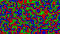
The animation above shows contours of constant radiation power density, propagating outward with time, traced in a plane that passes through a vertically oriented dipole antenna. This is a two-dimensional slice of a three-dimensional radiation pattern.
Due to complexity, generally only a single contour (isoline or isosurface) is traced around an antenna to show far-field radiation patterns. The contour surfaces are centered around an antenna and the contour lines are centered on orthogonal planes that intersect the antenna, often around a line of symmetry. The Hertzian dipole above transmits very little to no energy in the vertical direction.


Three-dimensional radiation patterns projected (as two-dimensional diagrams) onto Cartesian axes. Based on a Mathematica model found here.
Different antenna designs produce different radiation patterns. The complexity of the pattern depends on the antenna's design and construction.
Antenna specification sheets sometimes come with three-dimensional projections. More often, we see a two-dimensional plot and must imagine the three-dimensional pattern.

Polar and Cartesian representations of a radiation pattern for a Yagi antenna. Image courtesy of the Virtual Institute of Applied Science.
Permittivity and Permeability
Permittivity
Michael Faraday noticed that when dielectrics (insulators) are placed in the gap between the plates of a parallel-plate capacitor, the capacitance increases. This phenomenon is due to charge polarization inside the dielectric medium.
Permittivity is a measure of how readily those charges can align themselves (polarization) in the presence of an electric field. Higher permittivity indicates greater resistance to forming an electric field, and also slower propagation of a disturbance through the medium.
A high-permittivity material that surrounds a low-permittivity material will not affect the frequency of oscillation, but the high-permittivity material reduces the speed of the wave's propagation. If we recall that wave speed is equal to the product of frequency and wavelength, we can see that if frequency remains the same, the reduction in speed must come with a corresponding reduction in wavelength. When the wave exits the high-permittivity material, the wave speed and wavelength increase.
When an antenna is embedded in a high-permittivity material, the size of the antenna can be reduced in accordance with the decreased wavelength of the electromagnetic waves in the immediate vicinity of the antenna.
Some early GPS antennas (f = 1.56 GHz) were 60 mm by 60 mm and several mm thick, with circuitry that further increased the unit's size. By pairing circuit miniaturization techniques with the latest generation of microstrip patch antennas embedded in high-permittivity materials, GPS units that include antenna and circuitry can be produced in a miniaturized 4 mm by 4 mm by 2.1 mm thick form factor.
Similar techniques are used to allow and cell phones to have resonant antennas that are substantially smaller than the wavelength associated with propagation in air.
When waves transition between materials of different permittivity, energy is reflected. If the wave moves from a low-permittivity (i.e., high-propagation-speed) material to a high-permittivity (i.e., low-propagation-speed material), the wave will undergo an inversion (that is, a 180-degree phase shift). The reflected waves can combine with new waves to produce the various interference patterns seen in An Introduction to Antenna Basics.

High-speed-to-low-speed wave transition. Animation courtesy of the Penn State College of Engineering.

Low-speed-to-high-speed wave transition. Animation courtesy of the Penn State College of Engineering.
See this article (PDF) for additional information on the technical aspects of antenna miniaturization and on the trade-offs involving bandwidth and gain when working with high-permittivity materials.
Permeability
Magnetic permeability is the ability of a material to store energy in magnetic fields. Recall that the signals emitted from antennas are in the form of electromagnetic radiation—both electric and magnetic fields are involved. Thus, it is not surprising that permeability, like permittivity, affects the propagation of electromagnetic waves. Indeed, both permittivity and permeability result in slower wave speed and decreased wavelength.

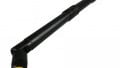
A ferrite rod loopstick antenna that has windings for medium- and long-wave AM reception. By Solaris2006 (own work) [CC-BY-SA-3.0].
To reinforce the idea that permittivity and permeability influence the speed (and the wavelength) of electromagnetic radiation, we can consider the "speed of light," which is actually the speed not only of light but of electromagnetic radiation in general. The speed of light in a vacuum—the fastest speed in the universe, denoted by c—is calculated using the permittivity and permeability of free space:
$$c=\frac{1}{\sqrt{\epsilon_0\mu_0}}$$
Directivity, Efficiency, and Gain
Isotropic antennas are theoretical point sources that spread electromagnetic energy equally in all directions. The total radiated power is determined by integrating the power flux density over the surface of a sphere of radius r that surrounds the antenna ($$\text{Surface Area}=4\pi r^2$$).
The integral represents the theoretical total radiated power. As the distance from the source increases, the surface area of the integrating sphere increases in proportion to the square of the radius of the sphere. The energy from isotropic emitters spreads out evenly to cover this increasingly larger area, and thus the electromagnetic power flux density decreases in proportion to the square of the distance from the source.

Since the power density of an isotropic emitter decreases rapidly with distance, antenna engineers manipulate the direction of energy radiated from real antennas so as to increase the power density in desired directions and reduce it in other directions.
Peak directivity (or simply directivity) is the ratio of the power density of the physical antenna in its most concentrated direction to that of a theoretical isotropic emitter of the same total power transmission level.
$$D=10\times Log_{10}(\frac{\text{actual antenna}}{\text{isotropic antenna}})$$
Directivity is expressed as an ordinary number representing the ratio or in dB, with larger numbers representing more focused beams. An antenna that radiated equally well in all directions would have a directivity of 1 (0 dB.) The Hertzian dipole presented earlier has a directivity of 1.5 (1.76 dB), owing to the lack of energy transmitted in the z-direction.
Antennas can be used in different applications based on their directivity:
- Low-directivity antennas transmit and receive information from all directions more or less equally. These are useful in mobile applications where the direction between transmitter and receiver can change.
- High-directivity antennas are able to transmit and receive information over greater distances but must be aimed towards another antenna. They are used in permanent installations such as satellite television.
Parabolic antennas (such as those used in satellite television receivers) have a typical "directive gain" (or simply "gain") of 37.5 dB. Antenna gain incorporates directivity as well as the efficiency of the antenna.
$$\text{Gain}=\text{Efficiency}\times \text{Directivity}$$
Efficiency accounts for the actual losses of a particular antenna design due to manufacturing faults, surface coating losses, imperfections, impedance mismatch, or any other factor. While directivity is always greater than or equal to 1 (0 dB), antenna gain can be less than 1 (0 dB).
Reflectors
The radiation pattern of an antenna gives us information about its receiving and transmitting properties in different directions. The radiation pattern can be shaped by adding directing elements (directors) in front and reflecting elements (reflectors) behind.
Reflectors redirect the energy that would radiate behind an antenna such that it propagates in the forward direction.
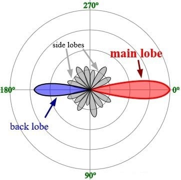
Image from Timothy Truckle (own work) [GFDL]. The antenna's forward direction corresponds to 0°.
An example of an antenna reflector can be seen in the following image of one of the Voyager spacecraft.

Voyager and its Cassegrain antenna. Image courtesy of NASA.
When receiving, it captures energy from a large area and reflects it toward a receiving element. When transmitting, it concentrates electromagnetic radiation along a central axis. The gain provided by antennas such as this one greatly aids in successful transmission of information over very long distances.
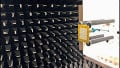
UHF television antennas, on the other hand, have reflecting elements on the far side of a folded-dipole receiving element; they collect and reflect (toward the receiving element) radio waves that would otherwise pass by.

UHF antenna with four reflectors on the far left. Image by Tennen-Gas (own work) [CC-BY-SA-3.0].
Directors
Like reflecting elements, directing elements are added to antennas to shape the radiation pattern. Their length and spacing are designed such that they absorb energy and reemit it in phase with the waves traveling directly to the receiving element or directly from the transmitting element. This creates constructive interference that applies only to the antenna's forward direction; waves that come from the side are absorbed and reemitted out of phase, leading to destructive interference.

Conclusion
You could make a career out of designing and testing antennas, but you will more likely be called on to understand the specification sheet of an antenna and how to incorporate the antenna into your design.
I hope this article and the one that preceded it in the series are able to provide you with a better understanding of antenna behavior and characteristics. Please feel free to comment here or post in the forum if you have further questions.
Related Content


“A high-permittivity material that surrounds a low-permittivity material will not affect the frequency of oscillation, but the high-permittivity material reduces the speed of the wave’s propagation. If we recall that wave speed is equal to the product of frequency and wavelength, we can see that if frequency remains the same, the reduction in speed must come with a corresponding reduction in wavelength. When the wave exits the high-permittivity material, the wave speed and wavelength increase.”
The para is little bit confusing. In beginning you say speed decreases but at last you say “wave speed and wavelength increase”. I think you missed to prefix “decrease” before “wave speed”.
Nice article by the way. Please keep sharing your knowledge 😊
Though not a physicist or engineer, I have studied sound waves in great detail. It is interesting to me that electromechanical waves share many of the same traits as sound waves. I had found out that light waves were also very similar to sound waves. I was told, but I don’t know if it is true, that light waves and radio waves were the same thing. Could you clarify, debunk, or explain that? I know they both travel through a vacuum.