 Facebook
 Google
 GitHub
 Linkedin
How to Decode Manchester-Encoded Data Using Hardware
This article looks at some circuits that can help you extract the original data from a Manchester-encoded signal.
This article looks at some circuits that can help you extract the original data from a Manchester-encoded signal.
Over a year ago I wrote about the “what and why” of Manchester encoding, and recently I continued this topic with an article that offers some guidance on how to convert your original binary data into Manchester data. So far so good, but Manchester encoding will be of little value in your communication system if you can’t convert a Manchester signal back into normal ones and zeros.
Slicing Data
One circuit that can come in handy in any Manchester receiver is something called a data slicer. We know that Manchester encoding is compatible with AC coupling and, when AC coupling is used, the average value of the received signal will be zero. However, the logic-high and logic-low characteristics may be less predictable, especially when the Manchester signal is exposed to significant noise or attenuation during its journey from transmitter to receiver.
A data slicer converts this noisy/attenuated waveform into a clean digital waveform by comparing the Manchester signal to the signal’s average value; the average value is extracted using an RC low-pass filter. If the incoming signal is above the average value, the comparator saturates at the logic-high voltage; if the incoming signal is below the average value, it saturates at the logic-low voltage.

As is usually the case with comparator circuits, a real-life implementation should incorporate hysteresis. If you plan on processing the Manchester data in a microcontroller, you could choose a device with a comparator module that incorporates programmable hysteresis. This would be a convenient way to slice the incoming data and deliver the resulting waveform directly to the processor that will convert the cleaned-up Manchester signal into normal logic-level data.
Decoding via Hardware
After data slicing, the receiver has a Manchester-encoded signal that conforms to expected logic levels and has no significant amount of noise. (Hopefully the comparator’s hysteresis was able to eliminate the spurious logic transitions that would otherwise occur when the noisy received signal crosses the comparator threshold.) The next task is conceptually simple, but not always so simple in real life: we need to interpret the positive and negative transitions as ones and zeros (or zeros and ones, depending on how you encoded the data).
It is possible to accomplish this task via hardware. I’m willing to bet, though, that most Manchester-based devices use firmware for decoding. The hardware implementations are somewhat complex, and they cannot compete with the flexibility and advanced functionality that is easily incorporated into a microcontroller or digital signal processor. However, hardware is faster and doesn’t consume CPU resources, so there is certainly value in pursuing a decoding solution that is based, at least in part, on hardware.
Microchip
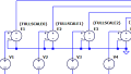
I found this first circuit in a Microchip app note. It’s not intended to be a standalone decoding solution; rather, they’re presenting an approach that can be implemented using hardware that they have incorporated into some of their microcontrollers, namely, configurable logic cells (CLCs) and a numerically controlled oscillator (NCO).

Diagram taken from a Microchip app note.
Cypress
The next circuit is from Cypress and is intended to be used with a PSoC 1 device.

Diagram taken from a Cypress app note.
Both of these implementations are interesting in that they do not recover the original data directly from the Manchester transitions, despite the fact that Manchester encoding is based on transitions. Rather, they take advantage of the fact that the original logic level is always present shortly before the transition. This will be more clear if we take a look at a Manchester timing diagram:

Let’s say that the active edge of the clock is the rising edge. If the data signal is low at the rising edge of the clock, the Manchester signal makes a low-to-high transition to represent the logic low. If the data signal is high at the rising edge of the clock, the Manchester signal makes a high-to-low transition. The Manchester signal always transitions when the clock has a rising edge.
Furthermore, the Manchester signal must prepare for this transition by moving, if necessary, to the state that allows it to make the required transition. If the Manchester signal has to make a low-to-high transition (corresponding to a logic low), it must be logic low before it makes this transition. If it has to make a high-to-low transition (corresponding to logic high), it must be logic high before it makes the transition. Thus, the logic level of the Manchester signal immediately before the transition is equal to the logic level of the original data.

Both the Cypress and the Microchip approach incorporate a delay that causes the circuit to sample the Manchester signal after three-fourths of the bit period has elapsed. This timing is based on the fact that the Manchester signal might need to transition halfway through the bit period (assuming that the bit period starts with the rising edge of the original clock, as in the diagrams above). By delaying for three-fourths of the bit period, the circuit is guaranteed to sample the signal after the mid-bit-period transition and before the active transition.
Creating the proper delay is easy if the receiver always knows the bit period that will be used by the transmitter, but even if it doesn’t, the receiver can recover the clock from the Manchester data stream. You can find more than you ever wanted to know about Manchester clock recovery in this Master’s thesis.
Silicon Labs
If you want to ponder one more decoder circuit, the following implementation (also based on the three-fourths-of-the-bit-period concept) was designed by SiLabs for use in its microcontrollers that include configurable logic units (CLUs).

Diagram taken from a Silicon Labs app note.
Conclusion
We looked at two circuits that can convert Manchester-encoded data to normal logic-level data and we also discussed a data slicer, which provides preliminary signal processing and is useful in conjunction with both firmware-based and hardware-based decoders. In a future article, we’ll explore the issue of receiver–transmitter synchronization in Manchester-based systems.


Nice to get another angle on this coding.
The nearest I got to good explanations and code implementation was on Nick Gammon’s site and there is an Arduino library for Manchester but I’ve never tried it.
What got me interested were the chips from RF Solutions (RF803E etc.). Under their sticky label was a Microchip MCU of some description. They do work well and I use them mainly for 433-MHz remotes. However, I never like the idea of relying on one supplier and reckon it’s better to come up with your own solution just in case they pull the plug on it.
I tried the Holtek chips for the same job, but they were too fussy about timing and never worked that well.
I’ll take a look at your other articles and have a crack at it one day