Facebook
 Google
 GitHub
 Linkedin
Interpreting Current-Voltage Curves of Different Materials
This article discusses the ideas involved in measuring and interpreting the current-voltage curves of solar cells, batteries, and unknown materials.
This article discusses the ideas involved in measuring and interpreting the current-voltage curves of solar cells, batteries, and unknown materials.
This technical article discusses the use of I-V curves of ideal, linear components to understand and interpret different materials and how they are used as electronic devices. In particular, the article covers solar cells, batteries, and new materials. While external references will be provided for how these devices work, this article will only focus on the I-V curves of these devices.
Suggested Reading
I-V Curves of Solar Cells
Solar cells are photoelectric devices that convert light energy into electrical energy. In other words, they generate power when exposed to light. When light falls on a photovoltaic semiconductor material (solar cell), energy from the photons transfer to the material, which produces freely-moving charges.
For a completed circuit with a load resistor, a current is generated in the circuit when the solar cell is exposed to light. Because the solar cell generates electrical current, its I-V curve is obtained by load switching.
Load switching involves the use of different resistor loads connected across a source of power and measuring the voltage across the device (using a voltmeter), as well as the current through it (using an ammeter). In order to see the extent to which a solar cell can provide current to a circuit, we measure the I-V characteristic of the device by using the load-switching method. A typical curve is shown in Figure 1.
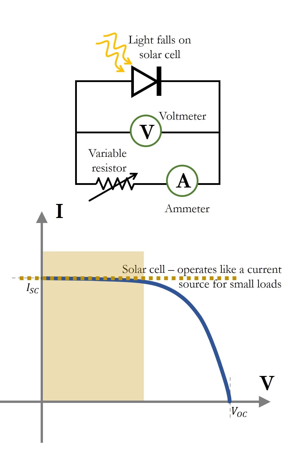
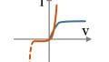
Figure 1. Schematic of an I-V measurement circuit for a solar cell for a fixed illumination (top) and a typical I-V curve of a solar cell (bottom). $$I_{SC}$$ is the short circuit current and $$V_{OC}$$ is the open-circuit voltage. For small resistor values, the solar cells tend to behave like ideal current sources.
For a resistor load of 0 ohms (short circuit), the maximum current that a solar cell can produce for a given incident illumination is known as the short circuit current, $$I_{SC}$$. On the other extreme, for a resistor load of infinite ohms (open circuit), there will be no current in the circuit, whereas the voltage generated by the solar cell for a given illumination is called the open circuit voltage, $$V_{OC}$$.
From the I-V response of the solar cell shown in Figure 1, we see that typical solar cells tend to behave more like a current source for smaller values of load resistors. On the other hand, a battery tends to behave like a voltage source, as we will see in the following section.
I-V Curves of Batteries
A battery, which is a collection of voltaic cells, is a device that converts chemical energy to electrical energy through electrochemical reactions. A battery is rated for a particular voltage and capacity rating (A-hr), based on its chemical construction and composition. Examples of battery types are Nickel-Cadmium (Ni-Cd) or Lithium-Ion (Li-Ion).
Because the battery is a source of power, the I-V response of a battery is obtained using load-switching. A schematic of the I-V curve of a battery is shown in Figure 2.
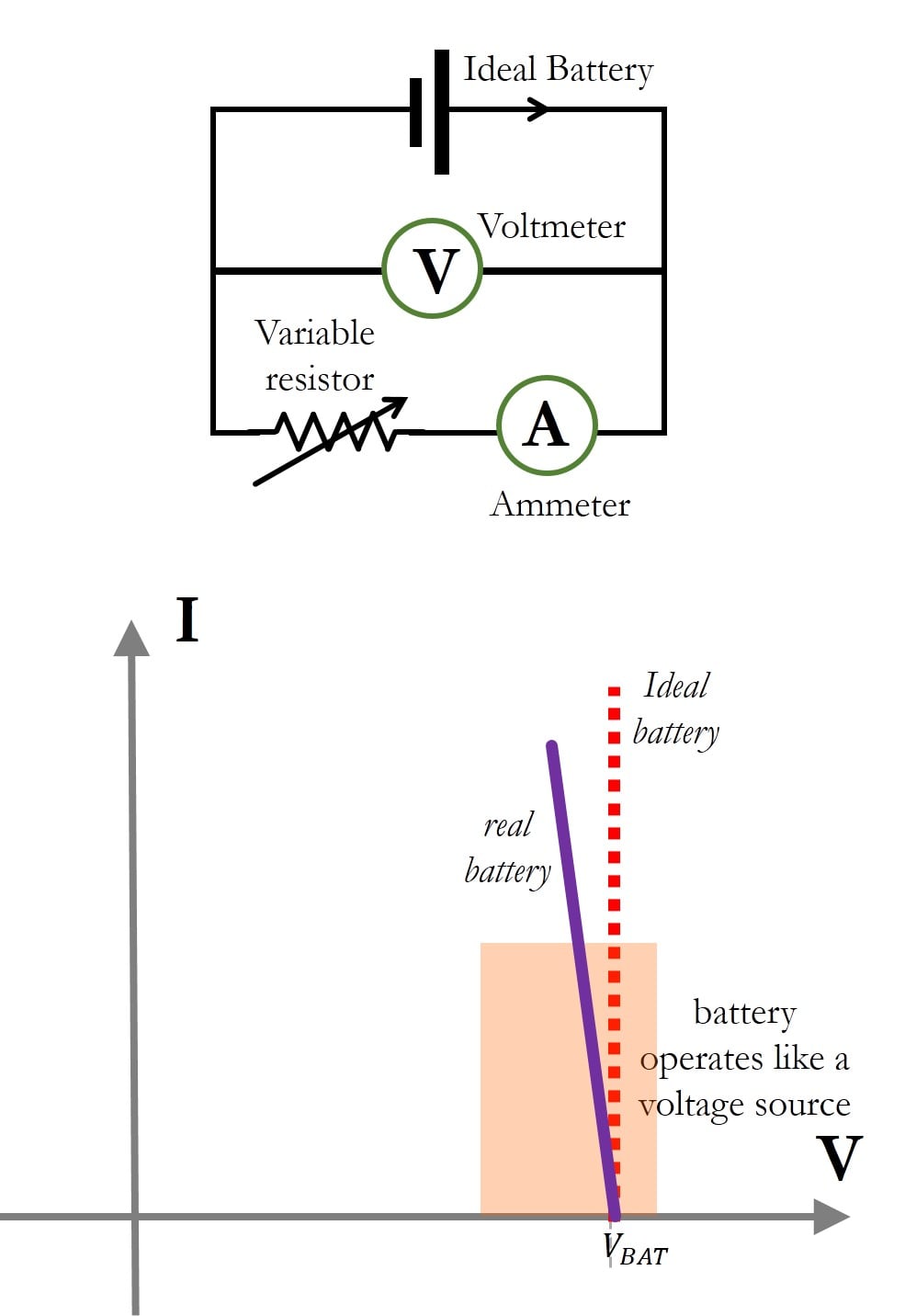
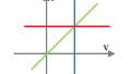
Figure 2. Load switching measurement of an ideal battery (top) and the I-V curve of an ideal battery as well as a typical real battery (bottom). The real battery is usually modeled as an ideal battery in series with an internal resistance, because of the linear nature of the I-V curve.
An ideal battery operates like an ideal voltage source. A real battery that is still fully functional behaves like an ideal voltage source, but it has a slope as shown by the solid line in Figure 2.
A slope on an I-V curve is a resistance (as described in the article on I-V Curves of Ideal Components). Therefore, a real battery is often represented as an ideal battery in series with an internal resistance, as described here. The I-V characteristic of a solar cell and a battery does not pass through the origin, indicating that they store some form of energy.
I-V Curves of New Materials
We have seen the current-voltage curves of ideal components, which are linear and passive devices such as resistors, capacitors, and inductors. We also looked at active devices that supply power such as ideal voltage sources and current sources.
Using the ideal plots, we looked at the I-V curves of non-linear, passive devices like diodes and transistors, as well as active devices such as solar cells and batteries. At one point in time, devices like diodes and solar cells were unknown, and measuring the current versus voltage characteristic was a way of modeling the device using linear components. Having a basic intuition behind I-V curves can help engineers discover new uses for materials.
In this section, we shall look at the I-V curve of a stimulation electrode, used for sending electric pulses in mammals. This section of the article just gives an insight into how we can use the I-V curves of linear components to visualize an unknown I-V response, and have an intuition as to how it behaves.
Neural Stimulation Electrode
An electrode is a conductive material that makes contact with a non-metallic part of the circuit. For example, batteries are constructed with electrodes placed in an electrolyte. In order to study the material used in an electrode, electrochemists perform a measurement known as cyclic voltammetry, which is essentially an I-V curve measurement using the voltage sweep method.
Cyclic voltammetry (CV) plots are methods of studying the voltages at which electrochemical reactions are most prevalent. In this regard, CV also accounts for the rate at which the voltage sweeps are being performed. You can learn more about cyclic voltammetry here.
The measurement setup for an I-V curve of an electrode is usually a three-electrode system. The electrode is placed in salt solution (NaCl) and there is a platinum counter electrode, as well as a reference electrode. The figure below is an example of the I-V response, or cyclic voltammetry plot of an iridium-oxide film electrode, used for biological stimulation applications.

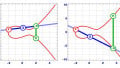
Figure 3. I-V curve of an iridium oxide electrode material placed in salt solution (blue curve). Also superimposed is the I-V curve response of a capacitor and a resistor. This shows that the material exhibits capacitive properties of charge storage (hysteresis)
The plot in Figure 3 shows the CV curve of an iridium oxide electrode. Unlike a resistor, observe that the electrode response of iridium oxide in salt solution incorporates the properties of a capacitor—that is, it stores charge. This charge storage property, along with many others, is the reason that this material is used for biological stimulation, which is the injection of charge into biological tissue.
Summary of Interpreting I-V Curves of Different Materials
| Devices | Requires Power? | I-V Method | Commonly Used As? | Passes through Origin? |
| Solar Cell | No | Load Switching | Current source for small loads | Yes |
| Batteries | No | Load Switching | Voltage source for large loads | Yes |
| Stimulation Electrode | Yes | Voltage Sweep | Behaves like a capacitor, used for injecting charge into tissue | No |