 Facebook
 Google
 GitHub
 Linkedin
Introduction to Bandgap Voltage References
This article presents some basic information about bandgap circuits, which are widely used to generate temperature independent reference voltages.
This article presents some basic information about bandgap circuits, which are widely used to generate temperature independent reference voltages.
The bandgap reference technique is one of the most commonly used methods for creating a temperature-independent reference voltage.
Bob Widlar, the legendary electronics engineer, laid the foundation for today’s bandgap voltage references in the late 1960s. Before that, the only semiconductor solution relied on using noisy, temperature-sensitive Zener diodes. In addition to these drawbacks, the Zener diode based method required supply levels larger than 5 V.
We will see that a normal bandgap voltage reference can generate reference voltages as low as about 1.23 V. Additionally, there is a group of bandgap references, called fractional bandgaps, that can create output voltages as low as a few millivolts.
What Is Bandgap Reference?
The goal of a voltage reference is to generate a stable voltage that is ideally independent of changes in temperature and other external factors. Unfortunately, the ambient temperature can affect the properties of the different components within a circuit.
For example, the base-emitter voltage of a BJT transistor is a linear function of the absolute temperature and exhibits a temperature coefficient of about -2 mV/°C. Such device limitations will affect the circuit output.
If we don’t have access to a better device, we’ll have to somehow compensate for the temperature-induced variations. For example, if we can generate a voltage that’s a linear function of the absolute temperature and has a positive temperature coefficient of 2 mV/°C, then we may be able to compensate for the variations introduced by the base-emitter junction.
One way of generating the 2 mV/°C temperature coefficient is by noting that the thermal voltage (VT) given by the following equation is a linear function of the absolute temperature:
$$V_{T}=\frac{kT}{q}$$
In this equation, k is the Boltzmann constant, q is the charge carried by a single electron, and T is temperature in Kelvin. The temperature coefficient of the thermal voltage is $$\frac{k}{q}$$ which is about +0.085 mV/°C. As you can see, the temperature coefficient is positive but it is much less than the desired value of 2 mV/°C.
To solve this problem, we can amplify the thermal voltage by a temperature independent constant M so that $$\frac{Mk}{q}$$ is equal to about 2 mV/°C. This concept, which is the main idea of a bandgap reference, is illustrated in Figure 1 below.
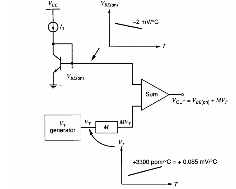
Figure 1 Image courtesy of Analysis and Design of Analog Integrated Circuits.
The thermal voltage is produced by the “VT generator” block. The output of this block is multiplied by an appropriate factor M and then added to the base-emitter voltage of a BJT. Ideally, the overall output should be independent of temperature.
A Basic Bandgap Has a Bow-Shaped Drift Curve
We assumed that the temperature coefficient of the base-emitter voltage is about -2 mV/°C; however, it’s not 100% constant. That’s why the bandgap output won’t be completely independent of temperature.
Only at one target temperature can we adjust the factor M to set the temperature coefficient of the reference output to zero. As the temperature moves away from this target, the temperature coefficient of the base-emitter voltage will slightly change. Consequently, the bandgap output will exhibit slight variations with temperature.
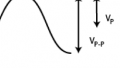
The typical output curve of a basic bandgap reference is as shown in Figure 2. Each curve corresponds to setting the temperature coefficient to zero at one particular temperature. As you can see, the output voltage of a basic bandgap reference has a bow-shaped drift curve when plotted against temperature.
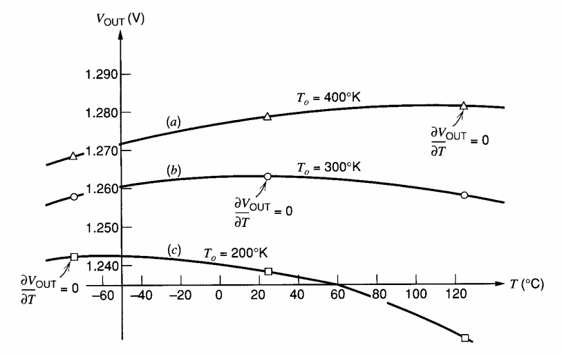
Figure 2 Image courtesy of Analysis and Design of Analog Integrated Circuits.
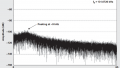
Some bandgap references use temperature compensation circuitry to further improve the drift performance of the basic structure. For example, the output of the LT1019, which is a precision bandgap reference, is as shown in Figure 3. This device employs a greatly improved curvature correction technique.
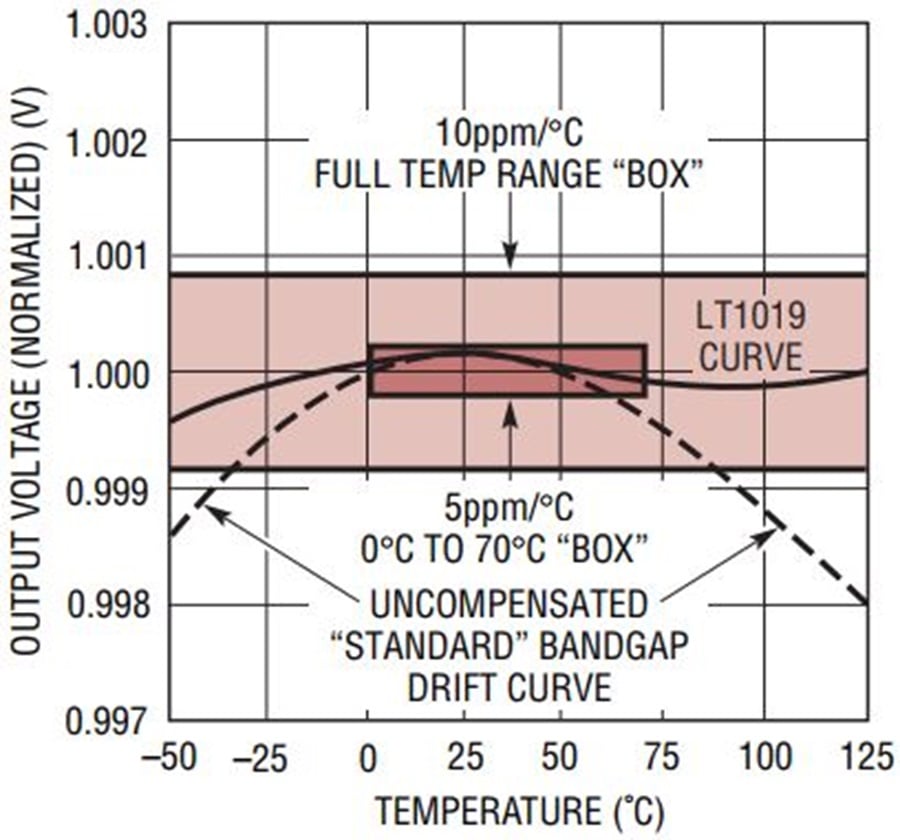
Figure 3 Image courtesy of Linear Technology.
Why Do They Call It a Bandgap Reference?
For the above discussion, we assumed that the base-emitter voltage has a temperature coefficient of -2 mV/°C and easily concluded that $$\frac{Mk}{q}$$ should be 2 mV/°C. To be more accurate, we should express the base-emitter voltage in terms of device parameters and use the obtained equations to calculate the factor M. For more information, you can refer to Section 4.4.3 of the book Analysis and Design of Analog Integrated Circuits. Here, we will only take a look at one final result of the analysis which gives the output voltage as:
$$V_{OUT}|_{T=T_{0}}=V_{G0}+\gamma V_{T0}$$
VG0 is the band-gap voltage of silicon, which is 1.205 V. γ is a parameter related to the doping level in the base. T0 denotes the temperature at which the temperature coefficient of the bandgap reference is set to zero. Hence, the thermal voltage, VT0, and the bandgap output, $$V_{OUT}|_{T=T_{0}}$$, are considered at $$T=T_{0}$$.
Assume that the bandgap output is set to zero at $$T_{0}=300 K$$. Hence, we have $$V_{T0}=26 mV$$. Assuming a typical value of γ = 3.2, we obtain
$$V_{OUT}|_{T=300 K}=1.205 V + (3.2\times 26 mV)=1.2882 V$$
As you can see the output voltage of a normal bandgap reference is close to the band-gap voltage of silicon, explaining the name given to this type of voltage reference. Now that we’re familiar with the basic idea of creating a temperature independent reference voltage, let’s take a look at the circuit implementation of this concept.
The Widlar Bandgap Reference
As illustrated in Figure 1, a bandgap reference needs to generate a voltage equal to the thermal voltage. Instead of generating a voltage equal to VT, we can generate a voltage that’s proportional to the thermal voltage. However, the proportionality factor should be temperature independent so that we can successfully apply the concepts discussed in the previous section. Let’s see if there is an easy way to achieve this. We know that the base-emitter voltage of a BJT is given by the following equation:
$$V_{BE}=V_{T}ln\left ( \frac{I_{c}}{I_{s}}\right )$$
where Ic and Is are the collector and the saturation currents, respectively. If Ic and Is were temperature independent, the base-emitter voltage would be equal to VT multiplied by the temperature independent factor $$ln\left ( \frac{I_{c}}{I_{s}}\right )$$. However, we know that the proportionality factor is not temperature independent. Let’s consider the VBE difference of two transistors Q1 and Q2:
$$V_{BE1}-V_{BE2}=V_{T}ln\left ( \frac{I_{c1}}{I_{s1}}\right )-V_{T}ln\left ( \frac{I_{c2}}{I_{s2}}\right )=V_{T}ln\left ( \frac{I_{c1}}{I_{c2}} \frac{I_{s2}}{I_{s1}}\right )$$
In this case, we can make the VBE difference a constant factor of the thermal voltage by making both the collector currents ratio ($$\frac{I_{c1}}{I_{c2}}$$) and the saturation currents ratio ($$\frac{I_{s2}}{I_{s1}}$$) constant. Scaling the emitter areas of the transistors allows us to set the saturation currents ratio. For the collector currents ratio, we can simply use current sources to set the bias current of the transistors. Thus, it is possible to make the VBE difference a constant factor of the thermal voltage. Bandgap references usually use the VBE difference of two BJTs to create the “VT generator” block in Figure 1.
As an example, let’s look at the simplified Widlar bandgap reference shown in Figure 4 below.
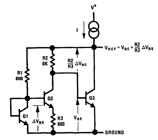
Figure 4 Image courtesy of IEEE Explore.
A loop is created by the VBE of Q1 and Q2 along with the R3 resistor. Hence, the voltage drop across R3 is equal to the VBE difference between Q1 and Q2. These two transistors are identical ($$I_{s1}=I_{s2}$$) but have different collector currents. Assuming that $$V_{BE1}=V_{BE3}$$, the resistors R1 and R2 have equal voltage drops. Therefore, the collector currents ratio $$\frac{I_{c1}}{I_{c2}}$$ is equal to the resistors ratio $$\frac{R_{2}}{R_{1}}$$ (we are neglecting the base currents of the transistors). Hence, the voltage drop across R3 is given by
$$\Delta V_{R3}=V_{BE1}-V_{BE2}=V_{T}ln\left ( \frac{I_{c1}}{I_{c2}} \frac{I_{s2}}{I_{s1}}\right )=V_{T}ln\left ( \frac{R_{2}}{R_{1}}\right )$$
Substituting the resistor values given in Figure 4, we obtain
$$\Delta V_{R3}=V_{T}ln(10)=2.3V_{T}$$
The current going through R3 is equal to that of R2, therefore we obtain the voltage drop across R2 as:
$$\Delta V_{R2}=\frac{\Delta V_{R3}}{R_{3}}\times R_{2}=\frac{R_{2}}{R_{3}}\times 2.3V_{T}=23V_{T}$$
The reference output is equal to the R2 voltage drop plus the base-emitter voltage of Q3:
$$V_{REF}=V_{BE3}+23V_{T}$$
Assuming $$V_{BE3}=0.65 V$$ and $$V_{T}=26 mV$$, we have $$V_{REF}=1.248 V$$. Moreover, we can substitute the temperature coefficient values for VBE3 and VT and calculate the temperature coefficient of the output:
$$\frac{\delta V_{REF}}{\delta T}\approx -2mV/^{\circ}C+23\times 0.085mV/^{\circ}C=-0.045mV/^{\circ}C$$
This is much less than the temperature coefficient of a base-emitter voltage. Typical bandgap references can achieve temperature coefficients as low as 20 ppm/°C.
Later Developments in Bandgap References
Widlar’s voltage reference, which was published in 1971, laid the foundation for today’s bandgap references. Despite being a great achievement, it had current drive sensitivity limitations. Moreover, it could not produce useful voltage levels such as 2.5 V and 5 V. These issues were later resolved by a groundbreaking design introduced by A. P. Brokaw. This was the first precision bandgap-based voltage reference.
Later, researchers developed bandgap references called fractional bandgaps that could output voltages as low as a few millivolts. For more information about this group of bandgap references, please refer to the JSSC paper, "A CMOS bandgap reference circuit with sub-1-V operation".
Today, bandgap references take on several forms but they usually rely on a bandgap core similar to that used in Widlar’s design.
To see a complete list of my articles, please visit this page.
Related Content


In Vout equation, 3.226mV should read 3.2*26mV.