 Facebook
 Google
 GitHub
 Linkedin
Introduction to QSPICE for LTspice Users
This article, the first in a four-part series on moving from LTspice to QSPICE, introduces an LED blinker circuit that we’ll simulate with both programs.
SPICE simulations are invaluable for testing, characterizing, and refining circuits that will eventually be built in the lab or produced as an assembled PCB. They’re also an excellent way—in my opinion, often the best way—of more thoroughly understanding how different circuits and their components function.
In short, SPICE simulators are crucial tools for modern engineers and engineering students alike. LTspice in particular has become something of a legend in the electrical engineering world. It’s powerful, widely used, and stocked with numerous IC macromodels. To top it all off, it’s completely free.
I’ve used LTspice for many years as both a design engineer and a technical writer, and I have great respect for its computing capabilities and diverse collection of analytical tools. As of 2023, however, there’s a new SPICE simulator in town: QSPICE.
Like LTspice, QSPICE was developed by Mike Engelhardt. It’s completely free to use, and—at least at first glance—it appears to offer everything LTspice does and more. If you perform circuit simulations that involve large amounts of digital logic, for example, QSPICE represents a massive improvement: it incorporates C++ and Verilog compilers that should allow you to conveniently and efficiently simulate extensive digital functionality.
According to Qorvo, the company that owns QSPICE, other selling points include faster simulations, higher accuracy, improved reliability, access to high-performance SiC models, and high-quality graphics. In a video introducing the software, Mr. Engelhardt goes so far as to state that QSPICE “is going to change your life.” Of course, these aren’t exactly impartial viewpoints. If we’re to consider migrating from LTspice, we need to know how well QSPICE lives up to its hype.
The best way to learn about new simulation software is to jump in and start simulating. In this article, we’ll create a circuit in LTspice and examine its current-voltage relationships. In subsequent articles, we’ll continue our analysis of the circuit in QSPICE. We’ll also discuss the challenges of moving the circuit schematic from one program to the other.
The Example Circuit
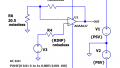
Figure 1 shows the circuit we’ll be examining: a two-transistor LED blinker based on the QTLP690C series from Fairchild Semiconductor.

Figure 1. [Click to enlarge] Schematic of a two-transistor LED blinker circuit in LTspice. Image used courtesy of Robert Keim
This is a simple circuit with complex operational details. There’s nothing too exciting about the overall functionality of an LED blinker, but even an experienced circuit designer might struggle to explain exactly how the electrical interactions of its components produce a short, periodic pulse of LED light. For those who are still relatively new to circuit analysis, or who mostly design digital circuits, the blinker’s operation might be downright baffling.
In that situation, the first thing I would do is fire up a SPICE simulator and start looking at voltage and current relationships—and that’s exactly what we’ll do, first in LTspice and then in QSPICE. Though this series is ultimately about the simulators, not the circuit being simulated, we should emerge with a better understanding of the LED blinker’s behavior as well.
With that, let’s get started on our simulations.
Key Currents and Voltages in LTspice
To determine the illumination behavior, we can run a basic transient analysis and plot the current through the LED. This is illustrated in Figure 2.
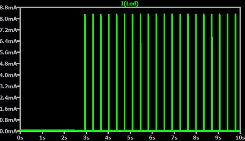
Figure 2. Current through the LED over a 10 second interval. Image used courtesy of Robert Keim
Figure 3 provides a zoomed-in view of the current when the LED is on.
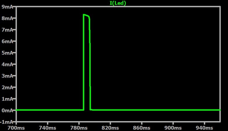
Figure 3. Current through the LED when the LED is on. Image used courtesy of Robert Keim
The blink duration is about 7.2 ms and we have about 2.8 blinks per second. Two questions immediately come to mind:
- What’s causing the delay at the beginning of the simulation?
- Is this enough forward current to illuminate the LED?
Let’s briefly answer both of these questions.
What Caused the Delay?
With a delay like that, we should instinctively suspect an energy storage element. To test that suspicion, Figure 4 adds a trace for the voltage across the blinker circuit’s capacitor (C1).
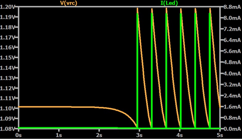
Figure 4. Current through the LED (green trace) and voltage across the capacitor (orange trace). Image used courtesy of Robert Keim
It’s clear from Figure 4 that the capacitor’s voltage is initially non-zero. Blinking only begins once the capacitor has discharged to a certain level. To correct this, we set the initial capacitor charge to zero in LTspice’s component attribute editor. This process is shown in Figure 5.
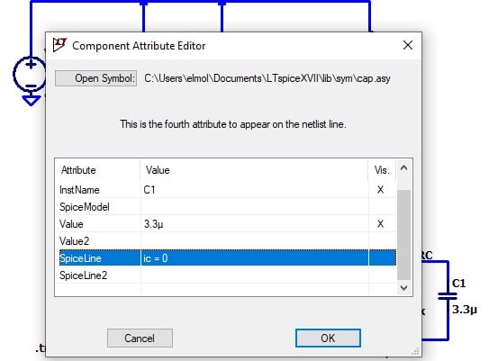
Figure 5. Specifying C1’s initial charge in LTspice’s component attribute editor. Image used courtesy of Robert Keim
Figure 6 shows the new simulation results.
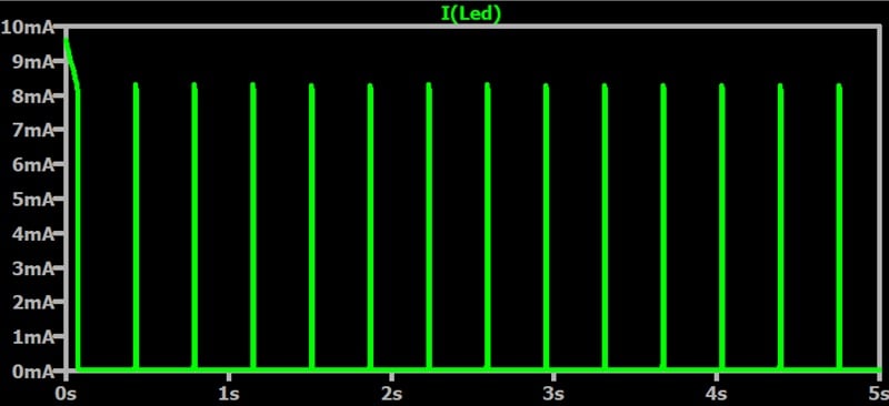
Figure 6. Current through the LED once with the capacitor’s initial voltage set to zero. Image used courtesy of Robert Keim
As you can see, we’ve successfully eliminated the delay.
Do We Have Enough Forward Current?
Our simulation plots show about 8 mA of forward current when the LED is on. To confirm that this is sufficient for LED illumination, we can check the datasheet corresponding to our SPICE model. As I mentioned earlier in this article, our simulated circuit is based on a QTLP690C surface mount LED lamp.
Figure 7 is taken from the QTLP690C’s datasheet. It plots the relative luminous intensity of the LED at 20 mA versus the DC forward current.
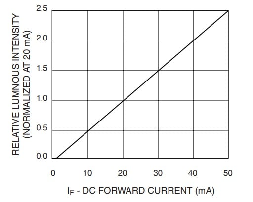
Figure 7. Relative luminous intensity (normalized at 20 mA) vs. DC forward current. Image used courtesy of Mouser Electronics
According to this plot, 8 mA of forward current will give us about 40% of the intensity produced at 20 mA. The typical luminous intensity at 20 mA is given in Table 1.
Table 1. Expected luminous intensity of a QTLP690C LED at 20 mA of forward current. Data used courtesy of Mouser Electronics
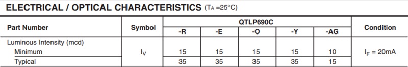
Except in the QTLP690C-AG, 20 mA of forward current typically produces 35 mcd of luminous intensity. 40% of that would be 14 mcd. That's bright enough to see, if barely.
Up Next
Though I'm wrapping up this article here, we're far from done with our analysis. In the next article, we'll move this circuit into QSPICE. Once we've done that, we'll use QSPICE simulations to gather additional information and piece it together into a more complete picture of the LED blinker's operation.
This article is Part 1 of a series on QSPICE for LTspice users. Below is a complete list of articles in this series:
- Introduction to QSPICE for LTspice Users
- Transferring LTspice Schematics to QSPICE
- Transferring SPICE Models from LTspice to QSPICE
- Using QSPICE to Understand and Tune an LED Blinker Circuit
Related Content


Are you sure about this blinker design? Are you using Q1 as a current source for the LED? Normally I would never design it this way, unless it is a bout some simulation detail you want to show us… You would not be able to control the current given by Q1, not a chance, would change with temperature like hell, most likely it would be close to saturation, blowing LED up…. Just saying…
Windows-only :(