 Facebook
 Google
 GitHub
 Linkedin
The Fundamentals of a Charge Pump Circuit
Dive further into switched capacitor circuits by learning about charge pump circuits, what they are, how they work, their pros and cons, and their applications.
In a previous article, we introduced the concept of switched capacitor circuits, how they work, and why they’re a valuable technique in analog circuit design. While there are many applications and use cases for switched-capacitor circuits, one of the most fundamental is the charge pump circuit.
With that in mind, let's explore charge pump circuits, the fundamentals of how they work, and their applications.
What is a Charge Pump Circuit?
A charge pump circuit, or charge pump regulator, is a kind of DC-DC converter that leverages switched-capacitor techniques to either increase or decrease an input voltage level.
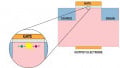
As shown in Figure 1, these circuit blocks generally consist of nothing but capacitors and switches (i.e clock-controlled field-effect transistors or FETs) and work by carefully timing and controlling these switches to exploit the charge transfer characteristics of capacitors. Discrete designs usually use diodes rather than transistors to implement the required switching operation.

Figure 1. Schematic of a simple charge pump circuit. Image used courtesy of Texas Instruments
Through alternatively charging and discharging capacitors, a charge pump can increase or decrease a given input voltage to the desired level.
From a lower-level perspective, charge pump circuits work on the basic principle that the voltage across a capacitor cannot change instantaneously. As defined by the capacitor I-V equation, in order for a capacitor to change its voltage instantaneously, it would require an infinite amount of current.
\[I_C = C \frac {dV_C}{dt} \]
Since this is not physically possible, we see that a capacitor cannot abruptly change the voltage across its terminals. Charge pumps work to exploit this behavior in order to manipulate the voltage across a capacitor through the use of carefully timed switches.
Charge Pump Voltage Doubler Circuit Example
To get a better understanding of how charge pumps work, we’ll now look at a fundamental example: the voltage doubler circuit.
As shown in Figure 2, our voltage doubler circuit consists of one single capacitor controlled by four surrounding switches.

Figure 2. A voltage doubler circuit schematic
The operation of this circuit is in two phases: the gain phase and the common phase. In the gain phase, SW1 and SW2 are closed while SW3 and SW4 are open. As shown in Figure 3, in this phase, the positive and negative terminals of C1 are connected to Vin and GND respectively.

Figure 3. In the gain phase, the capacitor is charged to Vin
As such the capacitor is charged up until the voltage across its terminals is equal to Vin. Now with C1 charged to Vin, we switch to the common phase shown in Figure 4.

Figure 4. In the common phase, the capacitor maintains the voltage across it by boosting its positive terminal to 2*Vin
In the common phase, SW1 and SW2 are open and SW3 and SW4 are closed. Here, the negative terminal of C1 is connected to Vin while the positive terminal is connected to Vout.
As established earlier, the voltage across a capacitor cannot immediately change. Because of this, the capacitor will try to maintain an equivalent voltage of Vin across itself. To maintain this Vin across itself, the capacitor forces the voltage at Vout to be equal to 2*Vin, making the equivalent voltage across the capacitor equal to Vin.
With the output voltage referenced to the ground, the voltage doubler circuit effectively takes an input of Vin and creates an output voltage of 2*Vin.
Non-Ideal Behavior in Charge Pump Circuits
It is quickly worth noting that our discussion thus far has assumed ideal capacitors and ideal switches, both of which are not realistic in real-world applications.
Some sources of non-ideal behavior in charge pump circuits include:
- MOSFET (metal-oxide-semiconductor field-effect transistor) switching losses
- Capacitor equivalent series resistance (ESR)
- Charge leakage
Each of these non-idealities can lead to lower efficiencies in charge pump circuits and slightly different behavior than modeled up by our equations and examples thus far.
Charge Pump Regulator: Advantages, Disadvantages, Applications
One of the major advantages of a charge pump regulator, as opposed to a switching regulator, is its significantly smaller size thanks to not requiring the use of an inductor.
Inductors are notorious for requiring a large amount of board space because the inductance value is directly related to the number of turns, and more turns require more space. Charge pumps, on the other hand, don’t require the use of an inductor, and as such are significantly smaller than switching converters.
Down below, Table 1 shows some of the main advantages and disadvantages between charge pumps, inductor-based switch-mode regulators, and low-dropout (LDO) circuits.
Table 1. Comparing advantages and disadvantages of charge pumps, switching regulators, and LDOs. Data used courtesy of Texas Instruments
| Type of Circuit | Advantages | Disadvantages |
|---|---|---|
| Charge Pump |
|
|
| Inductor-based Switch-mode Circuits |
|
|
|
Low-dropout (LDO) |
|
|
Charge pumps also have advantages over linear regulators, namely that they offer higher efficiencies and can both buck and boost an input voltage.
On the other hand, charge pumps tend to be less efficient than switching regulators, and have high levels of output ripple and noise, making them worse regulators than linear regulators. For these reasons, charge pumps are most suitable for applications that require a low load current and moderate input to output voltage difference.
Some popular applications for charge pump circuits include:
- Biasing Circuits
- Successive Approximation ADCs (Please see this paper for an example of this application)
- Electrically Erasable Programmable Read-only Memory (EEPROM)
- H-Bridge High Side Drivers (Please see this TI presentation to learn about the basics of this application)
In this article, we discussed an overview of charge pump circuits, how they work, and showed an example of a voltage doubler circuit. Along with this we discussed the trade-offs of a charge pump regulator and discussed how it compares with other popular types of voltage regulators.


Interesting article Jake but there are a few things you say that need a little qualification and maybe a few misplaced characteristics such as “clock feed through” which is a common problem with switched capacitor circuits used in filters but not so much in charge pumps.
The efficiency of an LDO depends on how it is used. If the LDO drops just a few hundred millivolts then even a 3V3 LDO could be 90% efficient. And a charge pump with a 200mA load will likely have woeful regulation wrt the no load condition.
I suspect Table 1 which is attributed to TI applied to a particular device or application and you have embellished it maybe? I say that because as a non specific summary it makes no sense. Besides the flaw I pointed out earlier the statement that a charge pump is more efficient than an LDO with the side niote of “+70%”. If you could have explained how it is that a charge pump can have better than the theoretical limit of 50% efficiency the article might have been really useful and properly educational.
As it is I am sorry but I have to push back when I see misinformation like this.
TI and others produce a number of highly integrated SMPS chips that operate at such high frequencies that the inductors are tiny as is the whole converter actually.
You are correct that inductors implemented in silicon is extremely rare but so is a capacitor big enough for a charge pump of the size you seem to be indicating. You also call them charge pump regulators. Regulation of their output voltage is simply something they cannot do without adding or deleting a stage. Otherwise the switches either operate in a linear region which ruins the efficiency even more or they must exploit some parasitic inductance somewhere to be a pseudo SMPS.
The only reason for a charge pump in a PLL is possibly for the VCXO (or variac etc ) for biasing purposes. Power for biasing circuits is by far the most common application of charge pumps so why single out PLL?
The article might have been good if you had a better grasp of the subject and better electrical training. Best not to propagate misinformation. Leave that to the politicians.
The list of applications given isn’t exactly helpful. I believe that two of the applications, while technically charge pumps, aren’t actually DC to DC converters as discussed in the article.
The notion of “ideal” behaviour in a charge pump is misleading, given a charge pump with a finite operating frequency and capacitance it will have a voltage drop due to the capacitor partially discharging each cycle. Starting with Q (charge) =CV=IT and leaving out those tedious integrals I get R=1/FC (no PI here as it isn’t a resonant circuit).
So if I use 1uF and 100kHz I get a resistance of 10 ohms, not bad but ... the ubiquitous ICL7660 runs at 10kHz by default hence their recommendation to use 10uF or more.
10kHz and 100n capacitors gives you about 1K effective resistance which isn’t really going to POWER anything but this might still be enough for some applications that really just need a voltage, for example a LCD module’s “VO” pin.
The successive approximation ADC circuit isn’t one most of us are going to build, it comes embedded in an IC, the same goes for EEPROM programming supplies, the charge pump is embedded in the IC and you’ll need a microscope to see it.
OK so one exception: the
The charge pump in the context of a phase-locked-loop is misleading. The sadly discontinued 74HCT9046 contained a charge-pump detector, this meant that the part had a current source and sink controlled by its phase detector. Each cycle the device would output a pulse of current, and the charge delivered by that pulse was proportional to the phase difference.