Facebook
 Google
 GitHub
 Linkedin
Understanding Types of Lock-In Amplifiers and Related Noise Sources
This article is a general guideline on the main aspects of commercially-available amplifiers.
In the previous article, we reviewed the fundamentals of lock-in amplifiers from a theoretical standout. In this article, we'll discuss the practical aspects of commercially-available lock-in amplifiers, including the different types of lock-in amplifiers and their main characteristics.
Since the purpose of a lock-in amplifier is to recover a signal from a highly noisy environment, one of the most relevant points when designing an experiment is the noise in the test set-up. As such, we'll also review possible noise sources in this article. Finally, we'll go over some of the lock-in amplifiers available on the market.
Types of Lock-In Amplifiers
Analog or Digital
When the first lock-in amplifiers showed up, all of its components (filters, multiplier, phase shifter, etc.) were purely analog. Due to the technology evolution as well as the lowering price of digital signal processors (DSP), some parts, such as filters or amplifiers, became digital.
Nevertheless, there are very specific situations in which having analog parts are quite useful. That's why some amplifiers still keep some of its components analog. In practice, the purely digital lock-in amplifier does not exist since stages like the input filter or amplifier remain analog.
Single- or Dual-Phase Detectors
As we saw when reviewing the homodyne transceiver in the previous article, the pillars of lock-in amplifiers use a reference signal to recover the in-phase (I) component; they also use the same signal shifted at 90º to recover the quadrature (Q) component. Hence, dual-phase lock-in amplifiers are those that detect both components while single-phase ones detect only the in-phase component.
The difference between dual-phase and dual-channel lock-in amplifiers can be confusing at times. Dual-phase lock-in amplifiers can detect both phase and quadrature components while dual-channel lock-in amplifiers can measure two different signals. Therefore, it is possible to have a dual-phase single-channel lock-in amplifier as well as a single-channel dual-phase lock-in amplifier.
Lock-In Amplifier Noise Sources
We have seen that lock-in amplifiers are a good tool when the goal is to recover a signal from a very noisy environment. When using a lock-in amplifier in an experiment aimed to fight noise, you must first understand where the noise comes from.
Thermal Noise
Thermal noise, also known as Johnson-Nyquist noise, is caused by the thermal fluctuations of stationary charge carriers, i.e. electrons. These fluctuations are caused by temperature variations and are independent of the applied voltage. Every resistor generates thermal noise and, according to the experiments carried out initially by Nyquist [1], can be expressed with the following formula:
\[V_{thermal}(rms)=\sqrt{4kTR\Delta f}\]
In this formula, k is the Boltzmann’s constant, T the temperature in Kelvin, \( \Delta f \) is the bandwidth, and R is the resistance value. This formula illustrates the importance of carefully selecting the resistor values of all the analog stages while reducing as much unnecessary bandwidth as possible.
Shot Noise
Current is caused by the flow of discrete charges—electrons or holes, depending on the type of junction. Since these charges are not continuous but discrete, the flow of the charges is not uniform, causing a statistical noise. This principle can be summed up in the following expression:
\[I_{shot}(rms)=\sqrt {2qI \Delta f}\]
Here, q is the electron charge, I is the RMS current applied in the circuit, and \( \Delta f \) is the bandwidth. When working with lock-in amplifiers, the input bandwidth is usually small, so the shot noise does not affect the measurements as much.
1/f Noise
Also known as pink or flicker noise, the exact origin of 1/f noise has not been exactly found, but it is well characterized in different components.
The amount of noise is inversely proportional to the frequency. That's why it can be difficult to perform accurate measurements on low-frequency experiments.
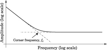
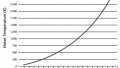
Power spectral density (PSD) of flicker noise. Image used courtesy of Behraad Bahreyni [2]
Pink noise presents a corner frequency fc, from where the noise is uniform. This frequency depends on the nature of each component (resistors, diodes, transistors, etc.).
For a more comprehensive discussion on electrical noise and where it comes from, you might review Robert Keim's technical article on the subject.
Choosing an Appropriate Lock-In Amp
Before selecting or building a lock-in amplifier for an experiment, you should be aware of a few key characteristics that may guide your decision.
Input Noise
Different types of noise, which are provoked by the internal components of the amplifier, will determine input noise present when you're taking a measurement. Since all the noise types are incoherent, the quadrature sum of all the noise components leads to the noise quantity at the input.
This number is always relative to the square root of frequency and its value is usually on the order of \(nV/\sqrt{Hz}\)
Minimum Dynamic Reserve
As we saw in the previous article on the fundamentals of lock-in amplifiers, the dynamic reserve is the ability to recover a signal from a determined noise level.
Since this value depends on the scale selected, manufacturers provide the minimum dynamic reserve in logarithmic units.

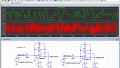
Specifications of the lock-In amplifier SR-844, indicating the minimum dynamic reserve. Image used courtesy of Standford Research Systems
Bandwidth
One of the most relevant aspects of a lock-in amplifier is the bandwidth, which specifies both the maximum frequency and the minimum frequency.
This minimum value is restricted due to the noise levels intrinsic to the internal components. The flicker noise is inversely proportional to frequency. Then, to guarantee the specified noise levels in all the frequency range, a minimum frequency has to be set in some lock-in amplifiers.
Old models present a bandwidth of 25 kHz to 200 MHz while most modern models can accept frequencies ranging from DC to 600 MHz.
Filters
The filter at the demodulation stage will determine the necessary time to complete an experiment as well as the quality of the output signal.
Manufacturers provide three parameters: time constant, filter bandwidth, and filter roll-off. All these three factors are interrelated and they provide the duration limits of an experiment as well as the type of signals that can be properly detected during an experiment.
Reference Signal
The accuracy of the reference signal is critical for the success of the experiments. The reference signal can be internally generated by a local oscillator or externally connected to one of the ports of the lock-in amplifier. In both cases, there is a maximum frequency—and sometimes a minimum—for this signal.
Phase specifications are as important as the frequency ones; the phase resolution and the phase error have to be low enough to have an accurate measurement. The phase noise, expressed in dBc/Hz, is also a critical parameter.
Commercial Models
Nowadays, there are different manufacturers offering lock-in amplifiers. Since a lock-in amplifier is such a specific instrument, the list of manufacturers is not huge. There is a discussion about who invented it, but the first papers showed up in 1941 [3].
In the table shown below, we compare some of the models that are in the market:
| Manufacturer | Model | Frequency Range | Min. Dynamic Reserve | Channel Numbers | Phase Resolution | Filter Roll-off(s) |
|---|---|---|---|---|---|---|
| Standford Research Instruments | SR850 | 1 mHz to 102.4 kHz | 100 dB | 2 | 1 m º | 6, 12, 18, 24 dB/oct |
| Zurich Instruments | UHFLI 600 MHz | DC to 600 MHz | 100 dB | 2 | 1 µº | 6, 12, 18, 24, 30, 36, 42, 48 dB/oct |
| Ametek | 7280 | 500 mHz to 2 MHz | 100 dB | 2 | 1 m º | 6, 12 dB/oct |
Conclusion
Lock-in amplifiers are very precise instruments that can be quite effective when recovering a weak signal from a high-noise environment. When selecting a commercial model, it is critical to check the noise level as well as its bandwidth and filtering capabilities.
References
- Nyquist, H, “Thermal Agitation of Electric Charge in Conductors”. American Physical Society, vol. 32, issue 1, 1928, pages 110-113.
- Behraad Bahreyni, “Flicker Noise”. Fabrication and Design of Resonant Microdevices, 2009.
- Michels, W. C.; Curtis, N. L., “A Pentode Lock-In Amplifier of High Frequency Selectivity”. Review of Scientific Instruments. Vol 12, issue 9, page 444.
Featured image (modified) used courtesy of Signal Recovery