Facebook
 Google
 GitHub
 Linkedin
Switched-Capacitor Filters
Figure 15-20 shows how rapid switching can cause a capacitor to act like a resistor.
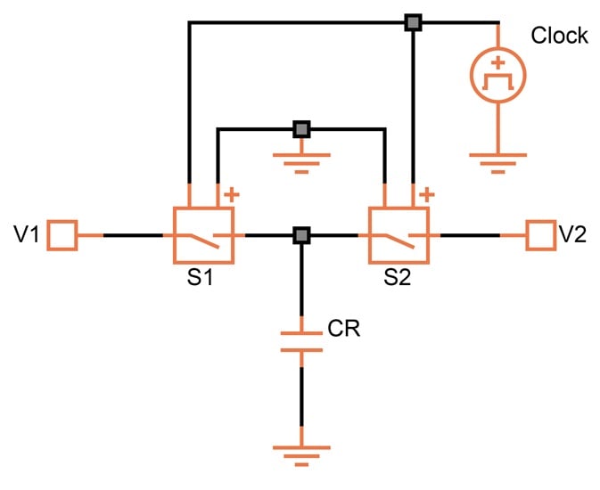
Figure 15-20. Making a resistor out of a capacitor by switching at a rapid rate.
If we charge a capacitor (CR) by closing switch S1 for a brief period of time, the potential across the capacitor is V1. Then, if we open S1 and close S2 for the same amount of time, the potential across the capacitor is V2.
The charge in a capacitor (in Coulombs) is given by either the capacitance times the voltage or the current flowing into the capacitor for a certain period of time. This is one of the handiest formulae to carry in your mind:
$$Q~=~C ~\times~ V ~=~ I~ \times ~t$$
In the case of Figure 15-20, the current flowing between the two terminals over one period is:
$$I ~=~ \frac {C_R (V_1~-~V_2)}{t_{clock}} ~=~ C_R (V_1~-~V_2) ~\times~ f_ {clock}$$
If we had a resistor between V1 and V2 instead of the switches and the capacitor, the current flowing through it would be:
$$I ~=~ \frac {V_1~-~V_2}{R}$$
Thus, the equivalent resistance of the switched capacitor is:
$$R ~=~ \frac {1}{C_R~\times~ f_{clock}}$$
Let's look at some numbers. Suppose the switching frequency is 100 kHz and CR = 5 pF:
$$R ~=~ \frac {1}{10^5~\times~5~\times~10^{-12}} ~=~ 2~\times~10^6 ~=~ 2 \ \text{M} \Omega$$
With a relatively small capacitor, we can create the equivalent of a large-value resistor. If we were to implement such a device directly, the cost in area would be prohibitive.
But the area reduction is just the first benefit of switching. There's more: if we use this resistor in a filter, the absolute capacitance value disappears.
A Simple Switched-Capacitor Filter
Shown in Figure 15-21 is a simple, one-pole, low-pass filter.
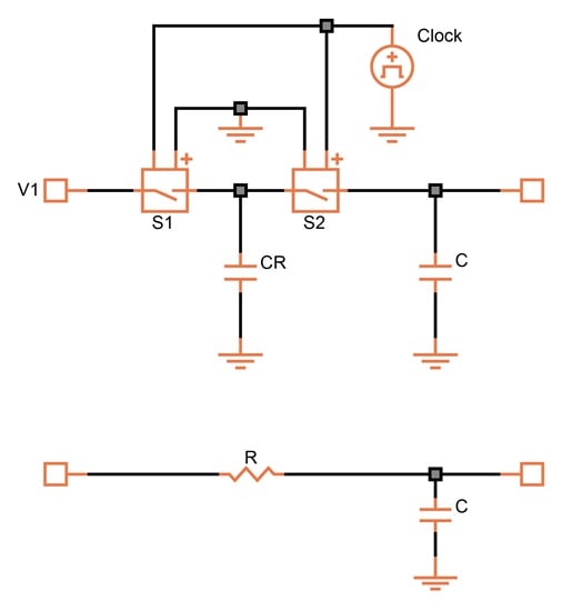
Figure 15-21. A switched-capacitor filter (top) and its equivalent RC circuit (bottom).
Because we're using the equivalent resistance of a switched capacitor in a filter, only the capacitor ratio and the clock frequency are important. The cutoff frequency is given by:
$$f_{3dB} ~=~ \frac {1}{2\pi R C}$$
Substituting the equivalent resistance of the switched capacitor, we get:
$$f_{3dB} ~=~ \frac {f_{clock} ~\times~ C_R}{2 \pi C}$$
If we give the two capacitors equal values and switch at a rate of 100 kHz, we get a filter with a cutoff frequency of 15.9 kHz. If C is ten times the size of CR and the clock frequency remains at 100 kHz, the cutoff frequency decreases to 1.59 kHz. Thus, the switched-capacitor filter has two significant advantages over the active (linear) one:
- A low cutoff frequency can be achieved with capacitor values small enough to allow integration.
- The cutoff frequency is not influenced by absolute variations. Given an accurate clock frequency and capacitor ratios of 1%, the cutoff frequency will be within 1%.
The simple low-pass filter can be expanded into any of the configurations discussed under active filters. For example, take the Sallen & Key filters in Figure 15-7. In a switched-capacitor design, you would first greatly reduce the values of the capacitors. You would then replace the resistors with a capacitor and switches.
The switched-capacitor filter requires lateral switches. Though easily implemented in CMOS, these are cumbersome and slow in a bipolar process. For that reason, the switched-capacitor approach has become exclusively CMOS territory.
Minimizing Stray Capacitance
To minimize the influence of stray capacitances, four CMOS switches are often used instead of just two. The result, shown in Figure 15-22, is an inverting configuration.
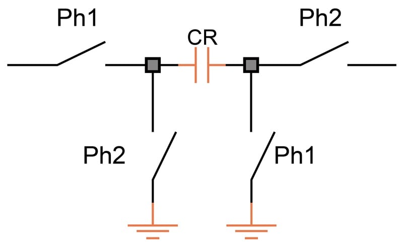
Figure 15-22. Switch configuration meant to minimize the effect of stray capacitances in CMOS.
For either switch design, it is important that the two lateral switches never be closed at the same time. There must be some dead time between the two phases (Ph1 and Ph2) of the clock.
Disadvantages of Switched-Capacitor Filters
Switched-capacitor filters have four main disadvantages. For one thing, no matter how carefully you design the switches, there is always some switching noise.
For another, a switched-capacitor filter samples the signal. To get an adequate sample, the highest signal frequency cannot exceed about 10% of the clock frequency. If there are signals present above that point, the switched-capacitor filter will produce a mixture of new frequencies, some of which may appear in the 0-to-10% frequency range.
To avoid such false signals, a linear (active) filter must be used at the input. This is known as an anti-aliasing filter.
The third disadvantage is that with an ordinary simulator, switched-capacitor filters can only be analyzed in real time. You can't take advantage of the many features of an AC analysis, such as measuring frequency and phase response. Furthermore, with the clock frequency necessarily being high, simulation takes far more time compared to an active filter.
Only if the simulator has additional features—time delay in the AC model, for example—can it give close to the same picture as that offered by linear AC analysis. There are some programs that have been designed exclusively for the analysis of switched capacitor filters.
Finally, the output has sampled noise even if the input is zero.