Facebook
 Google
 GitHub
 Linkedin
Volume
Designing Analog Chips
Chapter
Filters
High-Pass Filters
There is no mystery to converting a low-pass filter into a high-pass one. As the high-pass filter in Figure 15-14 illustrates, you simply exchange resistors and capacitors.
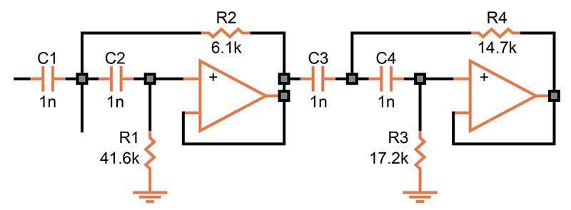
 Figure 15-14. High-pass Sallen & Key filter with Butterworth values.
As Figure 15-15 shows, the drop-off now occurs toward the low-frequency end. The slope is the same as that of a low-pass filter (80 dB per decade for a fourth-order filter).
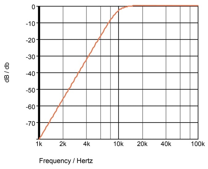
 Figure 15-15. Frequency response of the fourth-order high-pass filter from Figure 15-14.
Note that all of the schematics in this chapter use ideal op amps, meaning that our simulations use ideal voltage-controlled voltage sources. In a practical design, you have to consider the power supply. With a single supply, you may have to bias the input midway between ground and +V. In Figure 15-14, this is accomplished at the low ends of R1 and R3.